
Fig. 3: ToF imaging using the modulator and a standard camera.
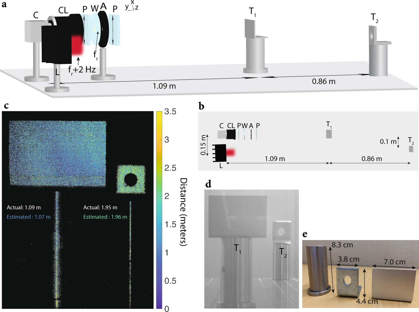
a Schematic of the imaging setup is shown. The setup includes a standard CMOS camera (C), camera lens (CL), two polarizers (P) with transmission axis \(\hat{{{{{{{{\bf{t}}}}}}}}}=({\hat{a}}_{x}+{\hat{a}}_{z})/\sqrt{2}\), wafer (W), aperture (A) with a diameter of 4 mm, laser (L) with a wavelength of 635 nm that is intensity-modulated at 3.733702 MHz, and two metallic targets (T1 and T2) placed 1.09 m and 1.95 m away from the imaging system, respectively. For the experiment, 140 mW of RF power at fr = 3.7337 MHz is used to excite the wafer electrodes. The laser is used for illuminating the targets. The camera detects the reflected laser beam from the two targets, and uses the 2 Hz beat tone to extract the distance of each pixel corresponding to a distinct point in the scene (see “Methods” for more details). b Bird’s eye view of the schematic in (a). c Reconstructed depth map seen by the camera. Reconstruction is performed by mapping the phase of the beat tone at 2 Hz to distance using Eq. (3). The distance of each pixel is color-coded from 0 to 3 m (pixels that receive very few photons are displayed in black). The distance of targets T1 and T2 are estimated by averaging across their corresponding pixels, respectively. The estimated distances for T1 and T2 are 1.07 m and 1.96 m, respectively (averaged across all pixels corresponding to T1 and T2). d Ambient image capture of the field-of-view of the camera, showing the two targets T1 and T2. e The dimensions of the targets used for ToF imaging are shown.
