
Abstract
In order to utilize the advantages of optical computing and promote the application and popularization of Ternary Optical Computer (TOC), this paper proposes a dual-center programming model consisting of electronic processor and optical processor, presents the theory and technologies of the dual-center model in detail, and for the first time explains the SAN ZHI GUANG (SZG) file chain technology, gives the implementation method of the dual-center model. The model tries to effectively manage the resources of optical processor and solve the problem of the distance and network connection mode of using the TOC. Experimental results show that the dual-center model is correct and the implementation method is feasible. It can improve the usability of the TOC and further simplify the TOC programming process, and makes common users apply the TOC and electronic computer to work cooperatively for the same task.
Introduction
Calculation speed has always been a concern of scientists, but the hardware of electronic computer is limited by Moore’s Law. Recently, many researchers are increasingly concerned about the study of new types of computers, such as quantum computer, DNA computer and optical computer and so on 1,2,3,4. Optical computing has advantages compared with electronic computing, in high parallelism, large number of processor bits, low power consumption and so on, so optical computer has become a common focus. In 2002, the theory of Ternary Optical Computer (TOC) was proposed4. The optical processor has a mess of processor bits and these processor bits can be grouped and reconstructed bit by bit, and computational function of each processor bit can be reconfigured at runtime.
Up to now, there are many meaningful achievements on the TOC. Decrease-radix Design Principle simplifies the optical computation structure5. The TOC task management software (TTMS) is the bottom control software of the TOC, which establishes the bridge of users using the TOC6. Computing—Data File and the computing-data model simplify the user’s process of using the TOC7,8. The optical processor bits management theory gives the management strategy and method of optical processor bit9. The Modified Signed Digit (MSD) adder10,11,12,13,14 and SJ-MSD adder15 make it possible for the TOC to solve real problems. The encoder and decoder make the ternary optical signal and binary electrical signal mutual conversion16,17. DFT algorithm implementation is an example of the TOC solving a real problem18. MSD Multiplication, parallel SRT integer divider and parallel radix-4 MSD iterative division make the TOC can solve more complicated multiplication and division problem.19,20,21. A three-lane CA traffic flow model improves the efficiency of computing in traffic problems22.
Although a lot of achievements have been obtained in the TOC research, it is still difficult for the common user to build application using the TOC. The advantages of optical computing are still not fully realized. The science and technologies in electronic computer are much mature. The common user maintains the habit of using electronic computers. The TOC and electronic computers cannot work together for the same task. In order to utilize the advantages of optical computing and promote the application and popularization of the TOC, how to make electronic computer and TOC collaboratively work for the same task becomes an urgent problem to be solved. Besides the resource manage for ternary optical processor (TOP) is still relatively weak, and the positional relationship and the network link mode between user’s electronic computers and optical computers needs to be considered.
To solve these problems, a dual-center programming model consisting of electronic processor and the TOP is proposed. The theory and technologies of constructing the dual-center programming model is discussed in detail, and the implementation method of the model is designed. The dual-center model effectively manages the resources of the TOP by using science and technology of electronic computer and improves the practicability of the TOC. The study achieves the cooperative work of the TOC and electronic computer and lays an important foundation for writing collaborative work application programs between electronic computer and the TOC. Meanwhile, it shows the advantages of optical computers in computing, which is helpful to solve the problem of parallel computing for big data.
Related works
The TOC architecture
In the TOC, information is expressed by no-light state and two mutually orthogonal polarized light states (such as horizontal polarization and vertical polarization)3,4, and the polarization directions of light is controlled by utilizing liquid crystal devices (LCDs). The TOC architecture consists of four main modules: light source, signal generator (encoder), TOP and decoder. The light source is used to generate the natural lights. The encoder converts natural lights into ternary light signals, which is used as the input signal of the TOP. The TOP is an LCD with a vertical polarizer and a horizontal polarizer attached on both sides, which is equally divided into four units (VV, VH, HH and HV) according to the direction of the polarizer. It is used to implement optical computing by changing the polarization state of light passing through LCD according to the relation between the light of the main and control light paths. The decoder converts ternary light signals into binary electrical signals. Refactor Latch is to temporarily store the reconstruction information. The reconstructor is to make the TOP reconstruct into required calculators. The structure of the TOC is shown in Fig. 1.

The TOC architecture. TOP: ternary optical processor.
The TOP consists of some simple basic units8. The structure of a basic unit is shown in Fig. 2. In the structure, P1 and P2 represent two polarizers. LC represents liquid crystal. f1 and f2 represent semi-reflectors. F represents the holophote. V represents vertical polaroid. H represents horizontal polaroid. g1, g2 and g3 represent phototubes, S represents tri-pick device. k1, k2 and k3 represent reconstruction instruction bits. Y represents XOR gate. There are two optical paths. The input data a enters the main optical path, the main optical path is a sandwich structure with a liquid crystal (LC) and two polarizers (P1 and P2). The input signal b enters the control optical path. The values of K2 and K3 determines that S selects an output signal from g1, g2 and g3 to the signal Y. In the main optical path, output signal of Y is used to control the LC’s optical rotation. When the value of reconstruction instruction bit k1 is 1, Y makes the S output signal negate, and when the value of k1 is 0, S output signal is unchanged. The difference between simple basic units is that the static rotation of LC is opposite, or polarization direction of two polarizers is different. The operands a and b are processed by TOP to obtain the result data beam C.

Simple basic unit structure.
MSD number
In the 1950s, the redundant counting method was used to eliminate the carry process in the addition23. In the 1960s, Avizienis proposed the Modified Signed Digit (MSD) digital system24. B.L Drake et al. introduced the MSD digital system to optical computing and studied the logical structures and optical implementation of addition25. Any decimal number N can be expressed in MSD number form (1).
where ai ∈ {0, 1, ī} i = 0, 1, 2, …, n. The common binary numbers are special cases of MSD numbers. For convenience, u will represent ī in the following of this paper, and N will be expressed as a string anan-1an-2 …a0.
MSD adder
Three steps TW-MSD adder is used in the TOC26. Mathematicians proved that the addition operation of two MSD numbers can be carried out by a series of appropriate ternary transformations26. The five logic transformations operations are T, W, T’, W’, S(T2), the transformation truth table as shown in Table 1. The parallel operation of MSD addition is as follows:
(1) T and W operation are performed for the operands a and b bit by bit, and one 0 is append ed to the tail of the result of T.
(2) T’ and W’ operation are performed separately to the results of T and results of W bit by bit. And one 0 is append to the tail of the result of T’.
(3) S operation is performed. The result of S operation is the sum of the operands a and b.
The theory and technologies of constructing a dual-center programming platform consisting of electronic processor and optical processor
TOC facing problems
The TOP faces new problems in two aspects: the TOP itself and the TOC programming platform.
For the first aspect, there are three problems. ① How does it assign processor bits to each operator? ② Before starting calculating, how are the structure parameters of every operator sent into the TOP. ③ In the program the massive original data are fed into the TOP by a simple way.
For the second aspect, the current programming environment cannot make the programmer control the processor bits allocation and the processor bit’s reconstruction in the application. Since,there is no simple way to send a mass of original data to the TOP, it is not possible to create applications that can take full advantage of the huge parallel computing power of the TOC in an existing programming environment. From the standpoint of programming application, to build the TOC programming platform, two key problems must be solved: ①Create a method to shield the TOP hardware and the underlying software for the programmer. The method can easily give play to the TOP application characteristics. ② Create instructions to call the TOP. Use these instructions to call the TOP to complete the specified calculation task without knowing the complex hardware structure and underlying software of the TOP.
The solutions of the problems
These two aspects are closely related, and need be considered at the same time. There are two intuitive solutions.
(1) Creating a new instruction set. Every instruction sends one kind of construction parameters of the composite operator or the original data to the TOC.
Advantages: The existing programming style is maintained.
Disadvantages: The programmer must understand the function of each instruction, the wrong order and parameter can’t be written in the program. on the other hand, there are so many construction parameters of the composite operator and the original data, so it is inevitable that the program will be very long and there are a large number of similar instructions sequence in program. Meanwhile, various programming languages all need the new instruction set. After updating the hardware and the underlying software of the TOC, the instruction set must be updated on time.
(2) Organizing the structure parameters of composite operators and all of original data into a special file, SZG file, and increasing some new instructions to send the SZG file into the TOC and then wait for the results returned by the TOC.
Advantages: Organizing SZG file and programming are completely parted. These jobs can be finished by different people. SZG file is used in various programming languages. The functions of the new increased instructions are very clear, so programmers can easily grasp them. Program will be concise by using SZG file; the existing programming style will be kept. After receiving the SZG file, the TOC can work, independent of the EC which is running the program, so the two types of computers are teamwork in one application. When the TOC being updated, SZG File’s format will be upgraded, but pre-existing SZG file is still available. For more than one SZG file received at same time, the TOC can schedule its data bits and jobs to improve the system utilization.
Disadvantages: It is a new method of programming, so it is strange to people.
The 2) has more advantages, and SZG file can conceal all details of the TOP hardware and the underlying software, providing users with a simple virtual machine of the TOC. The transfer of a SZG file is much more efficient than the communication method of transferring a datum by an instruction. The new instructions to operate the SZG file coincides with the instructions that call the TOP, the TOC TMS can allot processor bits according to the parsed SZG file information and these allotted processor bits can reconstruct into optical operators required by user 16. The SZG file method can integrate two aspects of problems. So the TOC research team chose the latter to create the TOC’s programming platform. SZG file becomes the core of using TOC in program.
At present, SZG file is the only way to express the user’s calculation rules and data bits in the TOC’s application7,8. In order to the TOC’s system software find user’s demands from a SZG file, users must follow a special format to create the SZG file. The new simplified version of SZG file format has two parts: SZG file head and data area as shown in Fig. 3. The SZG file head includes user’s information and demands for the TOP. The data section includes all of raw data in *.SZG file or all of computing results in *-R.SZG file. In the SZG file head, there are one File mark and n + 1 Calculation labels ranging from 0 to n. The File mark records the SZG file’s version, the SZG filename, user’s IP address and Label amount in the SZG file. Each Label records a user’s demand, which contains the calculation rule, data binary bit’s number, data amount and the first data address in the data section. In a SZG file, programmers can at the most give n + 1 calculation needs. In the *.SZG, the raw data of each Label are stored in the data section one by one, and the results are stored in the *-R.SZG. The starting address of each raw data or result region is recorded in the First data address of corresponding Label.

The simple SZG file format.
SZG file serves as a bridge between user and the TOC. SZG is the first letter of SAN ZHI GUANG in Chinese Pinyin. For details of the SZG file, please refer to reference7,8.
The TOC task management software
The TTMS is not only a bridge to the TOC, but also as a supporting software of the TOC. TOC’s processor bits are allocatable and bit-wise reconfigurable, so traditional task management software is not suitable for the TOC. The TOC needs a task management software suitable for its own characteristics. The TTMS needs to include the following functional modules, as shown in Fig. 4.

The function modules of the TTMS.
Request receiving module is responsible for receiving SZG files sent by user’s program. The task generation module is responsible for generating tasks to be processed by the TOC task management. Task parsing module is responsible for parsing information in SZG file to obtain optical processor bit allocation information and calculation information. The processor bit allocation module is responsible for allocating the required optical processor bits for a specific task. The reconstruction module is responsible for generating the reconstructed frames required by the optical processor according to the specific task. The reconstructed frame is sent to the control software of the TOP by the TTMS, then the TOP is reconstructed into the desired operator. The calculation module is responsible for generating calculation operands and completing calculations. The result file generation module is responsible for collecting the result data returned by the control software of TOP and generating the result file. The communication module is responsible for the interaction between the TOC and the user. It sent the result file to the user program. For the details of the modules interface, modules timing and the workflow, please refer to the literature6.
The initial SZG file generation software
The control information for the TOP is included in the SZG file. In order to facilitate SZG file generation, the TOC team created the SZG file initial generation software27. The software SZGSRRJ-LS2015 contains three main functional modules.
-
(1)
Information input module: This module function is to assist users in inputting information to construct SZG files, and it is also to check the format and format matching of the input information.
-
(2)
SZG file generation module: The module function is to organize the information sent from the input interface in an SZG file.
-
(3)
Operation result display module: This module function is to display the operation results, its function area is in the rightmost column of the input interface.
Run the SZG file generation program on user’s computer, and the interface shown in Fig. 5 appears. Input the required information on the interface. After the information check is normally finished, the user clicks the button of “Save SZG File”, then the user finds the SZG file on the current folder.

Input interface for computing-data.
The SZG file transfer software
User’s SZG file needs to be transferred to the TTMS, so electronic computer on the user side needs to generate the SZG file transfer instructions. Generating new instructions of using SZG file is equivalent to build a TOC command system in essence. From the standpoint of programming application, the new instruction system should be compatible with the existing instructions, so a simple way to form the TOC command system is to add instructions of controlling the TOP and a set of the SZG file chain instructions to the existing program language of electronic computer28,29. Obviously, the new command system is suitable for the TOC and electronic computer, and can compile the application programs which the two types of computers cooperatively work.
At present, the extended statements for C28, C + + and MPI29 have been completed. The C language extension is SZGCYYgh201228, the SZG file transfer software contains 4 extension functions, as shown below.
void SZG Init(): Its main function is to establish a communication connection with the TOC TMS. It must be the first SZG class extension in the program and only needs to be run once in a program.
int SZG Send (char * path): Its main function is to send the SZG file pointed to by the address pointer to the TOP.
int SearchResult (char * path): Its function is to query the current status of the *.SZG file pointed to by the address pointer on the TOP.
void SZG Suspend(): it is used to suspend the program until the operation result file is returned.
In the program void SZG Init() must be the first SZG class extension and only needs to be run once in a program. In order to recognize these four extended instructions in the C compiler, the header file of the application must also include SZG.h.
SZG file chain instructions
In some tasks, if some intermediate calculation results need to be used as calculation data in another cycle, then these calculation results are returned to user’s program, and they are written into another SZG file. The TOP carries out the new SZG file at the right time. Or the data in a new SZG file comes from other SZG files. Under these circumstances, the SZG file chain is needed. The SZG file structure is mainly divided into three parts: file parameter area, calculation labels parameter area, and data area7,8. According to this feature, the SZG file chain command group is divided into eight instructions. The functions of these instructions are as follows.
SZG_New_File instruction: Its function is to open the SZG file according to the target file name given by user’s program. If the specified file does not exist, a new SZG file is created with the file name, and the file name and version number are written to the new file.
SZG_Write_Fileparameter instruction: Its function is to open the SZG file according to the target file name given by user’s program, and write the operation label name and operation label character to the file.
SZG_Write_OperationIndicator instruction: Its function is to write the operation label name, the number of data bits a, the number of data bits b, the displacement, the number of data to be read, the number of result bits, the calculation rules and other data into the target file given by the user.
SZG_File_Data_b instruction: Its function is to read data from the data area of the specified operation label data b in the specified source file, and then write these data into the data area of the specified operation label data b in the specified target file.
SZG_File_Data_a instruction: Its function is to read data from the data area of the specified operation label data a in the specified source file, and then write these data into the data area of the specified operation label data a in the specified target file.
SZG_Add_Data_A instruction: Its function is when the user finds that the data in the generated SZG file is insufficient, and the lack of data is relatively small, you can use this instruction to add in the form of an array.
SZG_Add_Data_F instruction: The main function is to write the data in the file with added data to the data area of the specified operation label in the specified target SZG file.
SZG_Integrite_Test instruction: Its function is to check whether the newly generated SZG file is completed and whether any data is missed.
Each of the above instructions performs its own duties, and their responsibilities are different from each other. Use them correctly when it is needed, a complete SZG file will eventually be generated. This paper only briefly introduces the SZG file chain instructions, and the details of the use of SZG file chain instructions will be given in another paper.
A dual-center programming platform consisting of electronic processor and optical processor
The dual-center model is shown in Fig. 6. Each processor has its own operating system. The TOP includes an auxiliary processor to perform various routine tasks, such as the management of the TOP’s computing tasks, memory, SZG file transfer and the TOP reconstruction and so on. Most of these tasks are the same as the routine tasks of electronic computers and the operating system of electronic computers has perfected these technologies, so an electronic processor (EP) is currently used as an auxiliary processor, which runs a conventional operating system. This auxiliary processor makes the TOP make full use of the various achievements of computer science and technologies to improve efficiency of the TOP.

Dual-center architecture. OS: Operating System; TOP: Ternary Optical Processer.
Coupled with the TTMS6, the optical processor control software, the processor reconstruction software and the SZG file transfer software 27, which form the underlying software system of the TOC. Based on the underlying software, through adding the initial SZG file generation software and the expanded program languages with these transfer instructions, a dual-center programming platform is basically formed. In practice, the programming platform is running on programmer’s electronic computer, so the application programs and SZG files are stored in the external storage of programmer’s computer. When running the application, it sends a SZG file to the TOP for calculating, and waits for the results returned by the TOP. In this platform, programmers can write the application program to use the TOC and electronic computer without caring about the hardware features of the TOC and the communication process between the two cores.
The new programming platform is currently consistent with the electronic computer in application construction techniques, thereby it effectively reduces programmers’ strangeness and making programmers keep traditional programming ideas and techniques in a much familiar programming environment. It is convenient to use TOP’s huge parallel computing power and we can write the cooperative work application of the TOP and the EP in new platform.
In the model, there are four connection modes of the two computing cores.
-
1)
When the distance is far between the EP and the TOP, the two cores are connected through the network. In this case, the two operating systems share dotted line which is named as the network communication link.
-
2)
When the distance is near between them, both can be connected via USB, and the dotted line shared by the two operating systems is a USB link.
-
3)
When two computing cores are in a single chassis, EP can simultaneously serve as the auxiliary processor of the TOP.
-
4)
When the TOP is located in the supercomputer system as a computing node, electronic processor in Fig. 6 represents one or more electronic computer nodes, and they are connected to each other through the intranet of the supercomputer.
According to the above description, a clear calculation model is established, as shown in Fig. 5. As can be seen from Fig. 6, no matter how the two computing cores are connected, the programmer sees only a coincident programming platform.
The implementation method of dual-center programming platform
Considering the convenience of user programming and keeping the habit of running application programs, when designing the work mode of dual-center model, it is recommended to run the application programs on an electronic computer. The un-running SZG files and calculation result files are also stored in the external storage of user’s terminal. The SZG file will be sent to the TOC when the application program runs to an appropriate time. Although the TOC calculates the data in the SZG file much faster than electronic computer, it still takes relatively long time. Experienced programmers can let electronic computer run other tasks after sending the SZG file to the TOC, just check whether the calculation result file is returned after a period of time, so that two computers can serve one task. Obviously, under this circumstance, the TOP can be regarded as the “coprocessor” of electronic computer, but in the program with SZG file calculation as the core, electronic computer can be regarded as the “data preprocessor” of the TOC. It seems more appropriate to regard the two kinds of computers as cooperative machines that accomplish the same task.
In order to understand the working process of the dual-center mode, its workflow is shown in Fig. 7. The left part is the client workflow and the right part is the server workflow. The main process of the model is as follows.

The workflow of dual-center model.
Step 1: In the client, install auxiliary plug-in SZGX, run the initial SZG file software to generate user’s *.SZG file, input the required information on the interface. After the information check is correct, click “save SZG File”. Check the current folder and *.SZG file is created.
Step 2: Establish a connection between the client and server. If the connection between user and the TOC is successful, the communication between user and the TOC is correct. Or it is unsuccessful, if it is failure to establish a connection, please reconnect until the connection is successful.
Step 3: After the connection is successfully established, user’s program sends *.SZG to the TOC. The server sends a message to user’s program in the client. After user’s program receives the message, it is suspended by the instruction of (void SZG_Suspend ()).
Step 4: After user’s program in the client is suspended, in the server, the TTMS receives *.SZG. If the file name *.SZG sent by user program is the same as *.SZG received by the TTMS, it means that the TOC can correctly receive user’s SZG file.
Step 5: After the TOC correctly received user’s SZG file, the TTMS parses it, then generates reconstruction information and calculation information according to the information carried in the SZG file. And the TTMS sends these information to the optical processor control software.
Step 6: The optical processor control software on the slave computer allocates optical processor bits based on the reconstructed information, then the optical processor control software starts the optical processor reconstruction software, and the optical processor reconstruction software reconstructs the optical calculator needed by the user according to the reconstruction information.
Step 7: The TTMS fetches the original data in *.SZG file according to calculation information, the original data are arranged into a data frame. Then the data in the data frame are sent into the corresponding calculator, and the result light beams are obtained.
Step 8: The optical processor control software sends the result beams into the decoder, and then the corresponding results in binary are obtained. The optical processor control software sends these corresponding results in binary to the TTMS. And the TTMS collects the results data into the result file *._R.SZG.
Repeat Step 7 and Step 8 until the computation results of all original data in *.SZG file have been collected into the result file *._R.SZG.
Finally, the TTMS returns the result file *._R.SZG to user’s program in the client. Obviously, the programming platform keeps the advancement of the necessary technology, traditional programming concepts, habits and techniques.
After sending an SZG file by “int SZG Send (char * path)” instruction in user’s program, the programmer has two ways to wait for the result file returned by the TOC. Firstly, suspend the user’s program by using “void SZG Suspend ()” instruction, and the program is waken up when the result file is returned, and some of the computation resources occupied by the application can be released during this period. Secondly, the result file is queried at an appropriate time by “int SZG SearchResult (char * path)” instruction, the application can do other work between the two queries, which achieves cooperative work of the TOC and electronic computer. It chooses the first method in the paper.
The communication process of the two processors is as follows. Firstly, user’s program in the client sends his SZG file to the TOP in the server. When the TOP receives the SZG file, user’s program is suspended by the instruction of (void SZG_Suspend ()). Then the EP can transfer to other tasks, when the result file is return to user’s program, user’s program is woken up. And the TOP processes the newly received SZG files. When all data in the SZG file are been calculated, a result SZG file is generated. At this time, the TOP’s TTMS wakes up user’s program in the client. After user’s program is awakened, it will receive the result file sent by the TOP. For the identical task, the communication between the EP and the TOP is completed. The EP is responsible for submitting the calculation task and receiving the result files. The EP can do other tasks at other times.
Experiment and analysis
The experiments were carried out on the dual-center model including electronic computer and TOC-SD16. Electronic computer is 64-bit windows 10 operating system, Intel(R) Core(TM) i7-8565U CPU @ 1.80 GHz 8 GB. In TOC-SD16, for easy viewing of the resulting data, three adjacent pixels in the same row form a processor bit. Each pixel may output horizontal polarized light (H) or vertical polarization light (V) or no-light (W), the light intensity of W, H and V may be different. For an identical processor bit, there is only one output (W or V or H). The appearance of a basic module of TOC-SD16 is shown in Fig. 8. Processor bits are symmetrical. The processor bits structure in SD16 is shown in Fig. 9.

The appearance of a basic module of SD16.

Liquid crystal divisions 8.
Experimental instance: for four computational tasks, it contains four calculations with simple data type: P1 = a + b and P2 = c − d, P3 = e∧g and P4 = h∨i. Here “P1 = a + b” is the addition operation, the augend a and addend b are 8-bit MSD numbers, the sum is P1, and there are 200,000 pairs of original data. “P2 = c − d” is the subtraction operation, the minuend c and subtrahend d are 8-bit MSD numbers, the difference is P2, and there are 200,000 pairs of original data. “P3 = e∧g” means logical “AND” operation, the result is assigned to P3, “P4 = h∨i” is logical “OR” operation, the result is assigned to P4. Here e, g, h and i are 8-bit three-valued data, there are 100,000 pairs of original data e and g and 100,000 pairs of original data h and i. The result is P3 which is one of the value of the set {A, B, C}. The set of the result P4 is one in {X, Y, Z}. The instance information is contained in ZHSL.SZG file.
In the experiment, two computing cores is connected via USB. The experiment process is as follows.
(1) Install auxiliary plug-in SZGX in user’s electronic computer, run the initial SZG file software to generate ZHSL.SZG file, for the generation of ZHSL.SZG file, please refer to the literature 8. The generation of middle SZG file will be introduced in another paper.
(2) Build the connection between the client and the TOC. The user program starts a request to connect to the server TOC. The screen of successful connection is captured as shown in Fig. 10.

The connection success between the user and TOC.
(3) ZHSL.SZG is sent to the TOC.
User’s program sends ZHSL.SZG to the TOC, and the TOC TMS receives ZHSL.SZG. The file names ZHSL.SZG on user’s computer is the same as on the TOC. It means that the TOC successfully received the ZHSL.SZG file.
(4) The TTMS parses ZHSL.SZG and generates reconstruction information and calculation information according to the information carried in ZHSL.SZG file.
So ZHSL.SZG is parsed by the TTMS according to SZG file format 8 to get + , − , ∧ and ∨ four calculation rules and the corresponding data number (200,000, 200,000, 100,000, 100,000), 8-digit a and 8-digit b, 8-digit c and 8-digit d , 8-digit e and 8-digit g and so on.
(5) Allocate the processor bits required for the SZG file and reconstruct these processor bits with the corresponding calculation functions.
The sum of 8-digit a and 8-digit b requires 44 (= 8 * 5 + 4) TOP bits to construct a 8-digit TW-MSD parallel adder; similarly, the difference of 8-digit c and 8-digit d requires 44 (= 8 * 5 + 4) TOP bits to construct a 8-digit TW-MSD parallel adder 11; the ”∧” result of 8-digit e and 8-digit g requires 8 TOP bits to construct the 8-digit “∧”operator; similarly, 8 optical processor bits are required to construct the 8- digit “∨”operator.
The data amounts of P1 and P2 are twice that of P3 and P4. In order to improve the efficiency of the optical processor, the P1 operation is assigned two adders and the P2 operation is assigned two subtracters. the P3 operation is assigned one “∧” operator and the P3 operation is assigned one “∨” operator. Hence a composite operator consisting of 192 (= 88 + 88 + 8 + 8) optical processor bits is created. In SD16, the processor bits allocation of TW-MSD adder and logic operations is shown in Fig. 11. Each operation corresponds to a reconstruction instruction and 192 processor bits form a reconstructed latent image, then the latent image is sent to reconstruction register to achieve the reconstruction of the optical processor.

Processor bit allocation of the example.
(6) Calculate the data in ZHSL.SZG.
The TTMS sequentially takes out the original data in ZHSL.SZG, and generates data frames for these data, then these data frame are sent to the corresponding operator to be calculated in turn, and the result beams are obtained sequentially.
MSD adder is reconfigured in SD16. All calculation input data are MSD number. Here u represents the symbol ī, D represents decimal number. For P1 addition operation, the input data a are 10,001,001, 00101000, 00111001, 00100111, 01100101, 01001000 (corresponding to decimal number: 137, 40, 57, 39, 101, 72 respectively); The data b are 00101110, 01101100, 00100011, 01010100, 01111000, 10,100,011 (corresponding to decimal number: 46, 108, 35, 84, 120, 163). For P2 subtraction operation, the data c are 100u1010, 10uu0uu0, 110u0101, u0u010u0, u11u1011, 1010001u (corresponding to decimal number: 122, 74, 181, -154, -37, 161); the input data d are u0110011, 0u100101, 0u110111, u10101u0, 11,110,101, 110001u1 (corresponding to decimal number: 77, 27, 9, 46, -245, -195). For P3 “∧” operation, the calculation data e are 100u1010 (= 122D), 110u0101 (= 181D); The data g are u0110011 (= -77D), 0u110111 (= -9D). For P4 “∨” operation, the input data h are 10uu0uu0 (= 74D), u0u010u0 (= -154D); The input data i are 0u100101 (= -27D), u10101u0 (= -46D). The rest original data of the 4 operations do not be introduced.
The input data of the first screen is organized. For the first screen, one group of input data are 10,001,001( +), 00101000( +), 100u1010(-), 10uu0uu0(-), the another are 00101110( +), 01101100( +), u0110011(-), 0u100101(-). The data organization of the rest screens is similar.
MSD additions are completed in 3 steps with TW-MSD adder, and the logic operations are completed in 1 step. Hence the data of logic operation are just sent into TOP from the third screen. The results of the first three screens are captured.
The left (a) of Fig. 12 is the experiment results of the first screen in SD16 and the right picture is its theoretical analysis results. According to the arrangement the assigned processor bits in Fig. 11, No.0–63 processor bits are for T-transformation and W-transformation, which is in parallel. In the first screen of the T-transformation, we can see 1u00u0u1, 11,010,100, 00110110, 11,110,101 from the low-bit to high-bit. The results of these numbers in reverse order are 10,101,111, 01101100, 00101011 and 1u0u00u1. 10,101,111 is the result of 137 and 46 with T-transformation; similarly, 01101100, 00101011, 1u0u00u1 are respectively the result of 40 and 108, 57 and 35 as well as 39 and 84 with T-transformation. These values are the same as the theoretical analysis values of the right. Obviously, the W-transformation results are u0u00uuu, 0u000u00, 00u0u00u and u101001u, which are the same as the theoretical analysis values of the right (b) in Fig. 11.

The experiment result of the first screen.
Similarly, the left (a) in Fig. 13 is the experiment results of the second screen, the right (b) is its theoretical analysis results. One group of Input data are 00111001, 00100111, 110u0101 and u0u010u0, the other are 00100011, 01010100, 0u110111 and u10101u0. In TW area, they are the results of T-transformation and W-transformation for the second screen input data. In T’W’ area, they are the results of T’-transformation and W’-transformation in the first screen input data. The results of T-transformation are 00111011, 01110111, 10,100,111 and u1u111u0. The results of W-transformation are 000uu0u0, 0uuu00uu, u0u000u0 and 0u1uuu00. The results of T’-transformation are 000000000, 000000000, 000000000 and 0u0000010. The results of W’-transformation are 1u1u1100u, 010011u00, 001u1u11u and 101u10u0u. These values are the same as the theoretical analysis values of the right. The result analysis in remaining screens is similar to the screen.

The experiment result of the second screen.
The left (a) of Fig. 14 is the experiment results of the third screen; the right (b) is its theoretical analysis results. The results of T-transformation are 01111101, 11,101,011, 01101111 and 11,100,100. The results of W-transformation are 000uuu0u, uuu0u0uu, 0000uuu0 and 0uu00u00. The results of T’-transformation are 000000000,000000000, 000000000 and 00u100u00. The results of W’-transformation are 00110u100, 0100u110u, 1u1u01100 and u10000000. The results of S-transformation are 01u1u1100u (137 + 46 = 183),0010011u00 (148),0001u1u11u (45) and 0001u1000u (47). The result of operation “AND” is u00u0010 (−142). The result of operation “OR” is 1u1u01u1 (83). These values are the same as the theoretical analysis values of the right.

The experiment result of the third screen.
The calculation processes of the remaining data in ZHSL.SZG are the same as that described above. When the TOP calculates the data in the ZHSL.SZG file, user’s electronic computer can handle other tasks.
(7) Generate ZHSL-R.SZG, and return it to the user program. Hence the ZHSL-R.SZG can be found in the client computer.
The optical processor control software sends to the result beams to the decoder, and then the corresponding results in binary are obtained. The optical processor control software sends these results in binary to the TTMS, the TTMS answers for collecting the results into the result ZHSL-R.SZG and return ZHSL-R.SZG to user program.
A basic module of the TOP-SD16 has 192 processor bits, it can be installed up to 64 basic modules, which can be constructed 64 identical composite operators. And it can be constructed 64 identical composite operators. For the task, it only needs \({\lceil}100000/64{\rceil}\) = 1563 times operations to complete the calculation task. And for traditional model, it needs to perform 200,000 + 200,000 + 100,000 + 100,000 = 600,000 times operations. TW-MSD adder is three-step parallel pipeline process, as shown in Fig. 15. For the instance, all calculations need 100,002 operation (clock) cycles.
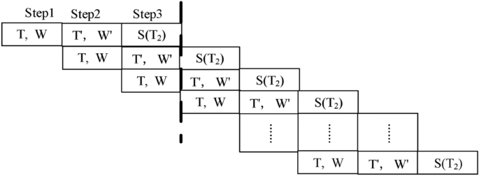
The pipeline process of three-step TW-MSD adder.
Assume that the reconstruction time of the TOP is T0, the number of processor bits is G, the number of operation (clock) cycles is Ty. So the amount of resource of processing the instance is G*Ty + T0. The TOP’s reconstruction time is 1 clock cycle, an addition operation needs 3 clock cycles. Suppose that an operation cycle is a clock cycle. For the instance, the computational efficiency of traditional model and dual-center model can be compared in consumed time and resource utilization, as shown in Table 2. It is shown that the clock cycle on dual-center model is only 0.2608% of on a traditional computer, and the computing resource spent on dual-center model is 25.04% of that on a traditional computer.
Through the experiments, it is known that each step of the experimental design is completed correctly, which indicates that the dual-center model is correct. In the model, the resource control software related to the TOP runs on electronic computer, so the science and technologies of electronic computer can be fully utilized, the utilization of the TOP is also improved. And when the TOP calculates the data in the ZHSL.SZG file, user’s electronic computer can handle other tasks. It achieves cooperative work for the same task between the TOC and electronic computer and keeps programmer’s programming habits.
The SZG file method is also its limitations. If the TOP cannot calculate 1000 times after one reconstruction, the two-center model is inferior to traditional computer. For large applications, if the intermediate calculation result data requires multiple iterations, the two-center model is also more troublesome than traditional computer, because the intermediate SZG files need to generate multiple times. The two-center model is best suitable for repeated calculation with massive data, without intermediate outcome data for multiple calculations. In the future, the two-center model needs to be improved, and the most likely method is to add a large memory to the TOP in the server, the large memory temporarily holds the intermediate result data for the next calculation, saving the time for the generation and parsing of SZG files.
Conclusion
It is apparent that optical computing is advantageous in some area. Such as parallel computing, low power, encryption, and so on. Through cooperating with the electrical computing, the optical computing becomes more practical, useful and meaningful. Therefore, this paper is aimed to the effective method of managing the TOC resources and the cooperative schemes between the optical computing and electronic computing. Specifically, a dual-center model is established, including the optical processor and the electronic processor, which demonstrates the relevant theories and technologies of collaborating the electronic computers and the TOC. On this platform, common users can write application programs can write applications in which TOC and electronic computers work together, without considering the location and the linking method of the TOC. Consequently, user’s programming habits remains, and the distance to the TOC can be neglected. Meanwhile, any mature electronic computer science and technology can be applied on the platform, no matter how the two computing cores are connected. Due to these advantages, the proposed method can be generalized to the electronic computing and other new dual-center computing models.
If the dual-center model applies to parallel computing in big data. The programmer only needs to generate a corresponding SZG file of the parallel computing task, and sends the SZG file to the dual-center model system in the application program, then the two-center model will be executed according to the workflow in the section "the implementation method of dual-center programming platform". But the current SZG file is not perfect, and it needs to be improved in practice. For the complex calculation SZG file, please refer to in reference 7. Subsequent developments will focus on the design of complex SZG file and the development of computational routines. The TOC team is working to apply TOC technologies to video encryption. For details, please follow the subsequent publication of the TOC team.
Data availability
The authors confirm that all data supporting the findings and research data of this study are available in the article.
References:
Merali, Z. First sale for quantum computing [J]. Nature 474(7349), 18 (2011).
Xu Jin. Probe Machine [J]. IEEE TRANSACTIONS Neural Network AND Learning Systems, 2016. JULY, 27(7):1405–1416.
Yi, J. I. N. He Huacan, Lu Yangtian. Ternary Optical Computer Architecture, Physica Scripta. T118, 98–101 (2005).
Jin, Y., He, H. & Lü, Y. Ternary optical computer principle. Sci. China Inf. Sci. 46(2), 145–150 (2003).
JunYong, Y. A. N., Yi, J. I. N. & KaiZhong, Z. U. O. Decrease-radix design principle for carrying/ borrowing free multi-valued and application in ternary optical computer [J]. Sci China Ser F-InfSci 51(10), 1415–1426 (2008).
Zhang Sulan, Jin Yi, Shen Yunfu, et al. Overview of the Task Management System of Ternary Optical Computer [C]. The 2016 IEEE Cyber Science and Technology Congress (CyberSciTech 2016). 8–10 Aug 2016; Auckland, New Zealand; Pages: 132–135.
Jin Yi, Zhang SuLan, Li Shuang, et.al. Computing-Data File: The Key Technology of Applying Ternary Optical Computer, Journal of Shanghai Jiaotong University (Natural Science), 2019, 53 (5): 584–592.
Sulan, Z., Junjie, P., Yunfu, S. & Xianchao, W. Programming model and implementation mechanism for ternary optical computer [J]. Optics Communications 428, 26–34 (2018).
Yi, J. et al. Management of many data bits in ternary optical computers [J]. Science China Information Sciences 43(3), 361–373 (2013).
Song, K. & Yan, L. Design and implementation of the one-step msd adder of optical computer. Appl. Opt. 51(7), 917–926 (2012).
Y. Jin, Y. Shen, J. Peng, et.al. Principles and construction of MSD adder in ternary optical computer [J]. Science in China Series F-Information Sciences. 2010.11, 53(11):2159–2168.
Peng, J. et al. Design and implementation of modified signed-digit adder. IEEE Trans. Comput. 63(5), 1134–1143 (2014).
Peng, J. & Ping, X. An optical implementation method for symmetric msd number, Optik - Int. J. Light Electron Opt. 143, 188–198 (2017).
Peng, J., Shen, R. & Ping, X. Design of a high-efficient msd adder. J. Supercomput. 72(5), 1770–1784 (2016).
Jiang, J. et al. The application of SJ-MSD adder to mean value filtering processing – ScienceDirect [J]. Optik 206, 164271 (2020).
Song, K. & Yan, L. The symmetric msd encoder for one-step adder of ternary optical computer. Optics Communications. 372, 221–228 (2016).
Jin, Y., Gu, Y. & Zuo, K. Theory, technology and implementation of decoder on ternary optical computer. Sci. China Inf. 43(2), 275–286 (2013).
Peng, J. et al. Implementation of DFT application on ternary optical computer. Optics Communications. 410, 424–430 (2018).
Ye, C. et al. Optical computer based application platform for MSD multiplication [J]. Optics Communications 458(12), 124814 (2019).
Jiang Jiabao, Sheng Yunfu, Chen Xunlei,etc. “Design and implementation of parallel SRT integer divider in Ternary Optical Computer [J], Sci. China Inf. Sci., 2021, 51(5):750–763.
Yunfu Shen, Sulan Zhang, Zhehe Wang, Weimin Li. Design and implementation of parallel radix-4 MSD iterative division of Ternary Optical Computer [J]. Optics Communications. 501(2021): 127360
Zhang Sulan, Shen Yunfu, Zhao Zheyu. Design and Implementation of a Three-lane CA Traffic Flow Model on Ternary Optical Computer [J], Optics Communications, 470 (2020): 125750
Booth, A. D. A signed binary multiplication technique [J]. Quart. J. Mech. Appl. Math. 4, 236–240 (1951).
A. Avizienis, "A Study of Redundant Number Representations for Parallel Digital Computers," Ph.D. dissertation, University of Illinois, Urbana, Digital Computer Laboratory, University of Illinois, Rept. No. 101; May 20, 1960
Patterson, R. H. & Miceli, W. J. Photonic computing using the modified signed-digit number representation. Optical Engineering 25(1), 038–043 (1986).
Jin, Y. et al. Principles and construction of msd adder in ternary optical computer. Sci. China Inf. Sci. 53(11), 2159–2168 (2010).
Li Shuang, Jin Yi. Simple Structured Data Initial SZG File’s Generation Software Design and Implementation [C]. 3rd International Conference on Wireless Communication and Sensor Network (WCSN 2016), Advances in Computer Science Research, 2016, 44: 383–388.
Huan, G. A. O., Yi, J. I. N. & Kai, S. O. N. G. Extension of C language in ternary optical computer [J]. Journal Shanghai University (Nature Science) 19(3), 280–285 (2013).
Zhang Qian, Jin Yi, Song Kai, et al. MPI programming based on ternary optical in supercomputer[J]. Journal Shanghai University (Nature Science), 2014.20(2): 180–189.
Sulan Zhang, Junwei Chen, Zihao Liu, Xiaolin Wang, Chunhua Zhang, Jun Yang. Key theories and technologies and implementation mechanism of parallel computing for ternary optical computer [J]. PloS one, 2023, Vol.18 (5): e0284700.
Acknowledgements
Thank Prof. Jin Yi, Prof. Shen Yunfu, Prof. Peng Junjie and all members of TOC team for their kind help and valuable discussions in preparing the paper. We also thank the Research Center of TOC at Shanghai University for the valuable equipment. This work is supported by General Scientific Research Project of Zhejiang Education Department of China (No. Y202352358) and National Science Foundation of China (No. 62302307) and Natural Science Foundation of Zhejiang Province of China (No. LQ22F020004) and Humanities and Social Sciences Research Special Project of the Ministry of Education of China (No. 23JDSZ3019).
Funding
General Scientific Research Project of Zhejiang Education Department of China,Y202352358,Humanities and Social Sciences Research Special Project of the Ministry of Education of China,23JDSZ3019,National Science Foundation of China,62302307,Natural Science Foundation of Zhejiang Province of China,LQ22F020004
Author information
Authors and Affiliations
Contributions
ZHANG Sulan wrote the original manuscript. LI Shuang achieved the initial SZG file generation software. LIU Jian achieved the SZG file chain instructions. FAN Xin and WANG Xiaolin edited the manuscript. TENG Zi and ZHANG Chunhua checked the manuscript.
Corresponding author
Ethics declarations
Competing interests
The authors declare no competing interests.
Additional information
Publisher’s note
Springer Nature remains neutral with regard to jurisdictional claims in published maps and institutional affiliations.
Rights and permissions
Open Access This article is licensed under a Creative Commons Attribution-NonCommercial-NoDerivatives 4.0 International License, which permits any non-commercial use, sharing, distribution and reproduction in any medium or format, as long as you give appropriate credit to the original author(s) and the source, provide a link to the Creative Commons licence, and indicate if you modified the licensed material. You do not have permission under this licence to share adapted material derived from this article or parts of it. The images or other third party material in this article are included in the article’s Creative Commons licence, unless indicated otherwise in a credit line to the material. If material is not included in the article’s Creative Commons licence and your intended use is not permitted by statutory regulation or exceeds the permitted use, you will need to obtain permission directly from the copyright holder. To view a copy of this licence, visit http://creativecommons.org/licenses/by-nc-nd/4.0/.
About this article

Cite this article
Zhang, S., Fan, X., Li, S. et al. Design and implementation of the dual-center programming platform for ternary optical computer and electronic computer. Sci Rep 14, 24696 (2024). https://doi.org/10.1038/s41598-024-75976-z
Received:
Accepted:
Published:
DOI: https://doi.org/10.1038/s41598-024-75976-z
Keywords
This article is cited by
-
Self-checking principle and design of ternary Berger code
Scientific Reports (2025)
-
Performance and energy optimization of ternary optical computers based on tandem queuing system
Scientific Reports (2025)
