
Abstract
Perovskite solar cells (PSCs) hold potential for low-cost, high-efficiency solar energy, but their sensitivity to moisture limits practical application. Current fabrication requires controlled environments, limiting mass production. Researchers aim to develop stable PSCs with longer lifetimes under ambient conditions. In this research work, we investigated the stability of perovskite films and solar cells fabricated and annealed in natural air using four different anti-solvents: toluene, ethyl acetate, diethyl ether, and chlorobenzene. Films (about 300 nm thick) were deposited via single-step spin-coating and subjected to ambient air-atmosphere for up to 30 days. We monitored changes in crystallinity, electrical properties, and optics over time. Results showed a gradual degradation in the films’ crystallinity, morphology, and electro-optical properties. Notably, films made with ethyl acetate exhibited superior stability compared to other solvents. These findings contribute to advancing stable and high-performance PSCs manufactured under normal ambient conditions. In addition, we also discuss the possible machine learning (ML) approach to our future work direction to optimize the materials structures, and synthesis process parameters for future high-efficient perovskite solar cells fabrication.
Introduction
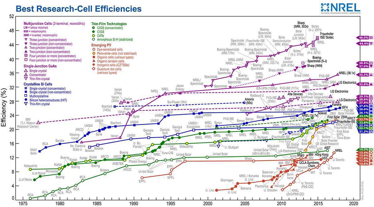
Perovskite materials exhibit excellent photosensitive and electronic characteristics such as broad absorption coefficients, extended carrier diffusion lengths, and large charge carrier mobility. These properties make perovskite materials attractive for a choice of optoelectronic devices, such as photovoltaic cells, light-emitting diodes (LED), photodetectors (PDs), and metal–semiconductor-meal photodetectors (MSM-PDs). Interestingly, the efficiency in converting power, often referred to as PCE, of solar cells made from perovskite materials (commonly abbreviated as PSCs) around 25% has been reported so far which is the result of advanced materials development and device engineering processes. The advancement mainly in materials synthesis and evaluation makes the PSCs now more closely competitive than those of traditional inorganic semiconductors thin film solar cells like copper indium gallium selenide (CIGS) and cadmium telluride (CdTe). It is predicted that the PCE of PSCs could reach beyond 25% soon due to the enhanced and controlled growth of perovskite layers1,2,3,4,5. A certified quasi-steady-state PCE of 26.15% for 0.05 cm2 and 24.74% for 1.04 cm2 perovskite solar cells has been reported recently in Ref6. The device exhibited 95% of its initial PCE after 1200 h at 65 °C under continuous operation. Besides, for practical applications, the persistent environmental durability over an extended period of PSCs is a crucial matter to address, which is currently considered prime research in this field of study. Exposure to environmental factors such as humidity, oxygen, heat, and light can cause degradation in PSCs, compromising their performance. To be suitable for commercialization, PSCs must demonstrate stability for nearly 25 years under outdoor conditions without significant surface degradation. However, the strength for PSCs is found about a year (so far, the longest period ever reported in the literature), which is significantly shorter than the commercialized PV technologies for example silicon solar cells. In particular, the stability and short lifespan of PSCs represent a significant obstacle to their commercialization in photovoltaics7,8,9.
The chemical constancy of PSCs is highly affected by the presence of two components (H2O and O2) in ambient air. It is reported that the perovskite layer in PSCs undergoes a color change from dark brown to yellow due to the surface and structural degradation occurs during the ambient environmental exposure. According to reports available in the literature, two possible reversible chain reactions cause very quick degradation of PSCs10. The combination of MAPbI3 and H2O drives to the creation of CH3NH2 plus [(CH3NH3+)n − 1(CH3NH2)nPbI3][H2O] which faraway disgraces into the [(CH3NH3 +)Pb3]n − 1, HI, Led-Iodide and water. Furthermore, CH3NH2 and HI gas easily affect the non-encapsulated device and/or non-degraded part and influence the degradation of that part. It has been reported by Snaith et al. that soft hydrogen bonding is likely to be formed in crystal composition during the perovskite formation which creates the unbound MAI. These MAIs escape easily from the perovskite crystal matrix, which sooner or later influences the growth of PbI2 and leads to degradation11. On the other hand, when exposed to humid conditions, the hydrolysis reaction of methylamine lead iodide (MAPbI3) can occur, causing the material to dissociate into MAI and PbI2 in the manifestation of moisture (H2O). Subsequently, MAI can decompose into HI (aq.) and CH3NH2 (aq.) as well. Liquidous HI can then respond with the air to form I2 (s) and water due to the Oxygen. Alternatively, HI may dissociate into H2 (gas) and I2 (salt). The utilization of HI by perovskite materials can impact the decay process and accelerate the reduction in PSC efficiency10. However, though a substantial quantity of research work has been conducted to investigate the degradation mechanism of perovskite materials including several reviews, and to overcome the stability issue of PSCs for further achieving highly performing and stable PSCs as well, still further research work is necessary8,9,10,11,12,13,14,15,16,17,18,19,20.
Perovskite films have already been prepared by using various fabrication technologies e.g. spin-coating21,22, sequential deposition23,24, and co-evaporation4,21,25 techniques followed by controlled temperature annealing processes including rapid thermal annealing (RTA)26. Among these methods, temperature-controlled spin coating technology is considered the simplest method ever to fabricate PSCs cost-effectively and eco-friendly. However, the growth of continuous perovskite films by spin-coating techniques using methyl ammonium halide and lead iodide (PbI2) mixed precursor solution is very challenging and yet to be addressed for future industrialization27,28. In particular, the solvent used in the foundation liquid plays an essential function in the formation of the perovskite thin film. The solvent influences the crystal growth and the resulting morphology that affects the visual, photosensitive, and electronic controls of the perovskite thin film. Employing anti-solvent materials during the fabrication process has been proposed to improve the film’s properties and stability. Anti-solvent materials potentially slow the solubility process of the perovskite precursor compared to the most used solvents. The addition of anti-solvent materials to the precursor solution is found effective in the formation of a more compact and uniform perovskite crystal structure leading to the improved physical, optical, and electronic properties of the resulting thin films. Toluene is found to be very effective as an anti-solvent chemical for obtaining quick crystalline perovskite films, however, other antisolvents like ethyl acetate, diethyl ether, and chlorobenzene also have potential for trials. The choice of anti-solvent has a significant impact on perovskite film formation and can potentially improve the stability of perovskite films which in intern can improve the perovskite-based solar cells as well. Additionally, non-fully covered perovskite films can be improved by investigating anti-solvent materials, especially for single-step spin coating techniques29,30,31,32,33,34,35,36.
In this study, we focused on the stability of perovskite materials and solar cells that were fabricated and annealed in natural ambient conditions using four different anti-solvents Toluene, Ethyl-acetate, Diethyl ether, and Chlorobenzene. The antisolvent selection approach took into account several aspects that impact crystallization processes and film quality, including diethyl ether, toluene, ethyl acetate, and chlorobenzene. Toluene and Chlorobenzene were selected as they can ensure homogeneous crystal formation. However, the non-aromatic solvents diethyl ether and ethyl acetate were chosen because they were expected to improve the film surface (smoothness) and enable quick solvent extraction. This wide range of choices was made to explore the rich avenues for achieving superior film shape and overall performance, including a variety of crystallization processes and their implications on the final perovskite films37,38,39,40. The perovskite films (around 300 nm thick) were fabricated using a simple spin-coater and stored in an air ambient (laboratory environment). The changes in the film’s quality and characteristics have been testified and investigated the effects of anti-solvent materials on the structural and optical properties of perovskite thin films. The obtained results reflect the potential of anti-solvent materials to improve the quality and stability of perovskite thin films, which can pave the way for the development of efficient and reliable perovskite-based optoelectronic devices.
Materials and methods
The chemical formula of perovskite materials is defined as ABX3, where A is a cation, B is a divalent metal cation, and X is an anion. The perovskite crystal structure is exemplified by a three-dimensional (3D) framework of corner-sharing BX6 octahedra, with A cations occupying the voids between the octahedral sites. The perovskite crystal structure can hold a wide range of cations and anions for the formation of various perovskite materials, including synthetic perovskite materials41,42,43.
Solution processing involves the deposition of a perovskite precursor solution onto a substrate followed by annealing to form a perovskite thin film. However, the quality and stability of perovskite thin films are highly dependent on the fabrication conditions and the properties of the materials used. The perovskite precursor solution typically contains a metal halide, such as lead iodide (PbI2), and an organic halide, such as methylammonium iodide. Commercially available FTO-coated glass substrates (10 sq) were cleaned by using an ultra-sonic bath and glass cleaning solvents commercially available in the markets. Then the cleaned glass substrates were subjected to be dried with pure nitrogen (N2) gas blown on a hot plate. A perovskite precursor solution (CH3NH3PbI3) was prepared by dissolving 461 mg PbI2 (purity of 99%, purchased from Sigma Aldrich) and 159 mg Methylammonium iodide (Dyesol) in 0.5 ml Dimethylformamide (DMF) and 0.2 ml dimethyl sulfoxide (DMSO). The solution was prepared in a glove box filled with N2 and maintained there for more than 8.0 h with the amounts of water and oxygen remaining below 1.0 ppm, and 200 ppm respectively. The solution was spin-coated twice, for 10 s at 1000 RPM and 20 s at 3000 RPM, onto a glass substrate that had been FTO-coated to create the perovskite layer. After 5 s, 100 µl of the required anti-solvent was tipped over the rotating glass substrate in the second step of the spin-coating process. The spin coating procedure was carried out in a laboratory setting with open air. The samples were moved to a hotplate that was situated in the same atmospheric condition as the solution preparation after the spin coating procedure was completed. The samples were exposed (heated) on the hot plate for 10 min at 100 °C (as presented in the schematic picture, Figure S1). Then the films were put in an environmental chamber of 50% RH, 2 to 5 lumens of light, and 30 °C ambient temperatures for continuous observation of degradation.
The PSC fabrication was followed by 100 nm of zinc-tin-oxide (ZTO) film preparation prior to perovskite films being spin-coated on top of ZTO films. The hole-extracting layer has been employed by a partial modification of the candle soot method. In this study, the calcinated carbon electrode via candle soot is used because it is potentially a hole-extracting electrode material that is inexpensive, stable, environmentally friendly, and abundant. A metal mask was placed on top of the FTO-coated glass substrate, and the candle soot films were deposited and then clamped with the FTO/ZTO/Perovskite stack after removing the mask. The fabrication process including cell structure is schematically shown in Fig. 1.

(a) Schematically shows the cell fabrication technique, (b) the structure of the solar cells, (c) a band diagram of the solar cell, and (d) an image of the fabricated sample.
The structural characteristics of the perovskite films were examined and investigated using X-ray diffraction (XRD) spectroscopy. Using a BRUKER aXS-D8 Advance Cu-Kα diffractometer and a Cu-Kα radiation wavelength of 1.5408 Å, the XRD traces were obtained in the 2-Theta range (20° to 70°). The results of the investigation into changes in microstrain, dislocation density, and structural disintegration are shown in the result section. Using Perkin Elmer Instruments Lambda35, UV–vis spectrometry is used to evaluate the optical characteristics. The Hall measurement equipment “ECOPIA 3000” was used to measure the carrier density, mobility, and resistivity. PL was measured at room temperature using a continuous wave laser of wavelength 452 nm utilizing the Edinburgh Instruments FLSP920 spectrofluorometer. Using Ag paste purchased from TED PELLA, INC, in the four corners of the films to measure electrical properties was determined.
Results
To explore the effects of anti-solvent materials on the structural and optical properties of ambient-fabricated perovskite thin films we conducted a series of experiments in preparation and characterization of perovskite films. The results obtained from these analyses revealed significant variations in the structural and optical properties of the perovskite thin films depending on the type of anti-solvent material used during the fabrication process. Figure 2 showcases the time evolution of the XRD of perovskite layers prepared on FTO coated glass substrate. The perovskite films prepared in room ambient remained in a humidity ambient of 45%RH for 30 days. The diffraction peaks are found at around 12.7, 14.2, 24.6, 28.5, 31.8, 38.7, 40.5, and 44.0, which correspond to a crystal plane of (001) (for PbI2), (110), (202), (220), (310), (224), (134) and (404), respectively20,21. One day of exposure revealed the peak with the (312) plane distinct to (114) and (310) (Fig. 2a,b). After three days of exposure, two further peaks with the (311) and (314) planes became evident, both suggesting the potential disintegration of the perovskite films.

XRD patterns of the perovskite films observed for different time durations (* sign indicates the position of the plan (110) of the perovskite films).
However, after seven days, it was seen that the peak elevation laterally of the perovskite plane (110) was gradually decreasing. This data demonstrates that the crystallographic perovskite structure is being consumed by the moisture-induced breakdown. The PbI2 peak (001) is a rising substitute for the perovskite (110) peak, as the PbI2 conversion resulted from the perovskite crystal breakdown (Fig. 2). Additionally, a gradual movement towards a lower angle in the peak position of the (110) plane is observed, indicating a rise in micro-strain and dislocation density. The mean crystallite sizes of the perovskite films may be impacted by the peak height’s decreasing over time. The breakdown of the films is further confirmed by the increase in the PbI2 peak, where PbI2 may form some point defects in the perovskite lattice that affect the atoms’ dislocation. To determine the crystallite size (D) of the fresh and 7-day-old perovskite films that were helped by anti-solvents, Eq. (1) was utilized in which λ is the wavelength (0.154 nm) used in XRD, k is the shape coefficient (0.9), β is the full-width half maxima, and θ is the diffraction angle (degree)44.
The introduction of several numbers of atoms and/or grains with varying relative positions and orientations during the recrystallization (drying process) of perovskite films can result in lattice misfit and strain. This is particularly evident in thin films where atoms are displaced from their reference-lattice positions, leading to the development of lattice strains. The resulting lattice misfit and strains caused by atomic displacement are characterized by micro-strain and can be estimated using a specific formula44 as shown in Eq. (2).
Further, crystallographic imperfection developed by the atomic dislocation could be recognized by calculating the approximate dislocation density in the film. Dislocations are typically caused by interstitial atoms or vacancies that differ from the surrounding atoms within the film’s crystals. As such, the dislocation density in a film can serve as an indicator of its crystallographic imperfection, which is associated with lattice mismatching. To calculate the dislocation density, Williamson and Smallman’s relation has been used in this study44. This relation provides a means of estimating the density of dislocations in the film based on specific parameters, allowing for a quantitative assessment of the crystallographic imperfection caused by atomic dislocation.
where D is the crystallite size.
Table 1 presents an overview of the crystalline size changes associated with the dissolution of perovskite thin films made using various antisolvents.
Figure 2a shows the variation of PbI2 conversion and bandgap properties. PbI2 conversion has been estimated using the following equation:
where “I” represents the intensity of the characteristic peak in the X-ray diffraction (XRD) pattern for the respective materials. For example, I(PbI2) refers to the intensity of the peak corresponding to PbI2, while I(Perovskite) refers to the intensity of the peak corresponding to the perovskite material.
Figure 3a shows that the micro-tension and dislocation degrees increase proportionately through the amount of decayed PbI2. This could be because more crystal defects and precipitates remain on the films. The impact of point defects on the film structure, including lattice misfit and dislocation, is widely recognized. For the understanding of the potential defects that may arise during the decomposition process and their effects on the perovskite crystal structure, readers are encouraged to review the relevant published works as well45.

(a) The degradation of perovskite films in terms of PbI2 conversion for different anti-solvent, (b) the variation of the optical bandgap as an impact of PbI2 conversion, and (c) shows the photograph of the perovskite films for fresh and 15 d of exposer.
The optical bandgap related to PbI2 conversion during the degradation of perovskite films is shown in Fig. 3b for a range of anti-solvents. The as-deposited films’ bandgaps for diethyl ether, ethyl acetate, toluene, and chlorobenzene are 1.57 eV, 1.57 eV, 1.55 eV, and 1.58 eV, respectively. However, there’s been an observed rise in bandgap following a 7-day exposure period. The film fabricated using toluene and Diethyl ether shows the highest bandgap increase which is consistent with the estimation of PbI2 conversion. Overall, the results reveal a clear relationship between anti-solvent selection and the degree of degradation observed in perovskite films. In general, films fabricated using Diethyl ether exhibit the highest degree of degradation, with approximately 75% of the initial films converted to PbI2 after 7 days of exposure in the ambient atmosphere. In contrast, films fabricated using Ethyl acetate exhibit the lowest degree of degradation, compared to other samples over the same period. These differences in degradation rates are reflected in the deviation of the spectral bandgap, as well as photographs of the films as shown in Fig. 3c. Overall, these results highlight the need for careful material selection and optimization in the fabrication process by indicating that the choice of anti-solvent compounds can significantly affect the stability and performance of perovskite thin films.
As it can be seen from XRD and UV–Vis spectroscopic analysis that the film fabricated using the Ethyl acetate shows better stability against the room’s environmental humidity and light, we tried to understand the PL characteristics of that film. Figure 4 shows the photoluminescence spectra for perovskite thin films fabricated using Ethyl acetate, both in their as-prepared state and after 7 days of exposure to ambient atmosphere.

Photoluminescence absorption spectra for perovskite film fabricated using Ethyl acetate (as prepared samples and the same samples after 7 days of exposure).
The results reveal a notable shift in the absorption peak position and a reduction in the photoluminescence intensity after exposure to the ambient atmosphere. Specifically, the as-prepared samples exhibit a sharp absorption peak at approximately 793 nm, whereas the samples exposed to the ambient atmosphere for 7 days exhibit a broader peak centered at approximately 771 nm attributed to the bulk recombination. Additionally, the photoluminescence intensity is significantly reduced in the exposed samples, indicating a loss of charge carriers and a decline in overall performance. The reduction in photoluminescence (PL) intensity can be attributed primarily to a decline in radiative recombination or an escalation in non-radiative recombination through the formation of defect centers, typically occurring in perovskite during the decomposition process, as detailed in Ref46. Furthermore, PL intensity reduction in perovskite materials (mostly with methylammonium lead halide perovskites) occurs due to their transformation of PbI2 which leads to changes in the crystal structure, band structure, and recombination dynamics of the material. Therefore, the efficiency of electron–hole recombination is affected, resulting in a reduced PL intensity as observed in studies of perovskite material degradation, emphasizing the importance of stability considerations in perovskite-based optoelectronic devices47,48. Photon-excitation phenomena and discharge from entangled recombined charged carriers in the superficial and/or band boundary level are likely to be the primary causes of PL broadening49. Peak shifting may also be associated with physical phase transitions and/or film decay. These observations suggest that exposure to the ambient atmosphere can significantly impact the optical properties and performance of Ethyl acetate-fabricated perovskite thin films, emphasizing the importance of careful environmental management during their fabrication and storage. Moreover, we also observed that there is a second PL peak at around 820 nm for both films which is attributed to surface recombination. A similar phenomenon has also been reported elsewhere50,51. The change in intensity as estimated by IA/IB has been observed to decrease for the exposed film indicating the increase of surface recombination and/or surface recombination becomes dominant in the exposed film. Alternatively, we can assume that the decomposition of perovskite films increases surface defects and/or recombination.
Table 2 provides a summary of the electrical properties of perovskite thin films fabricated using various anti-solvents, both in their as-prepared state and after 7 days of exposure to ambient atmosphere. The results reveal significant differences in the carrier concentration, mobility, and resistivity of the different films, highlighting the impact of anti-solvent selection on the electrical performance of the resulting films. Specifically, films fabricated using Ethyl acetate exhibit the highest carrier concentration, and films fabricated using Chlorobenzene show the highest mobility and comparatively lowest resistivity compared to the film prepared by Toluene. After 7 days of exposure to the ambient atmosphere, there is a general decrease in carrier concentration and mobility (summarized in Table 2) for all films, accompanied by an increase in resistivity. However, after 30 days, a drastic change in electrical properties was observed where the resistivity of the films was increased to the mega-ohm range, and films were converted to n-type. These changes indicate a complete transformation of perovskite to lead iodide which indeed reveals the complete degradation of perovskite materials and films. Furthermore, it was discovered that the sample prepared using ethyl acetate had a degradation rate that was significantly lower than that of the other samples, which may have been caused by ionic migration that occurred during sample preparation45. This was indicated by the variation of the normalized current density, voltage in the open circuit (Voc), current through the short-circuit (Jsc), as well as the efficiency throughout exposure (as shown in Fig. 5).

Time-dependent electrical properties variations observed in perovskite thin films.
The fact is the transformation from perovskite into PbI2 can certainly lead to a reduction in mobility and charge carrier concentrations. Perovskite materials act as semiconductors, however, the decomposed PbI2 becomes electrically insulators. Therefore, the increase in resistivity is a direct consequence of the reduction in mobility and charge carrier concentration that follows Ohm’s law, which states that resistivity is inversely proportional to both mobility and carrier concentration. Subsequently, due to the mobility and charge carrier concentration losses, there are likely to be higher resistivity increases in the films52.
These findings confirm that the selection of anti-solvent materials can have a significant impact on the electrical properties and performance of perovskite thin films and highlight the need for careful optimization and management of environmental conditions during the fabrication and testing of such films. In addition, the physiochemical properties (such as polarity, boiling point, and solubility parameters) of antisolvents and their influences on perovskite thin film formation kinetics can significantly affect the nucleation and crystallization processes of perovskite materials. For instance, the rate of solvent evaporation and crystallization may be affected by the distinct interactions that polar anti-solvents have with perovskite precursors. Similar to this, changes in boiling points can affect the pace at which solvent is removed, which in turn can change the content and shape of the film. Furthermore, SWOT analysis (Fig. 6) has been applied to understand the overall impact of all anti-solvent materials (Chlorobenzene, Diethyl ether, Ethyl Acetate, and Toluene) on the development of perovskite thin films fabricated under ambient conditions. Our study reveals that the utilization of anti-solvents advances substantial strengths, such as enriched crystallinity and improved optical properties, leading to a flexible method for tailoring perovskite thin film qualities. However, there are some limitations associated with the toxicity of certain anti-solvents and the possibility of having material incompatibility. On the other hand, the opportunities for processes and parameters optimization and application diversification were identified, besides the possible threats related to regulatory hurdles and inconsistent results. This analysis contributes to getting a comprehensive understanding of the prospects and challenges associated with anti-solvent materials processing in the domain of perovskite thin film development and technology, guiding future research directions and industrial applications as well.

SWOT analysis presenting the summarizing understanding of using anti-solvent materials in perovskite film development.
Significance and future motivation
We aimed to investigate the stability of perovskite thin films (expected to be better candidates for high-performing solar cell fabrication) and annealed in ambient lab conditions using various anti-solvents hold enormous implications for the development of renewable energy technologies. The variations in structural, optical, and electrical properties observed on the perovskite films over time pose an essential understanding of the stability and performance of perovskite thin films and solar cells. The obtained results indicate that stable and high-performance perovskite solar cells can be manufactured under normal ambient conditions, making them more accessible and cost-effective for common and extensive use. We believe that by addressing the issues of the degradation mechanisms and factors influencing perovskite stability, this research provides a foundation for future work. However, the integration of a machine learning approach in anti-solvent optimization further enhances the potential to tailor anti-solvent selection for improved stability, opening new avenues for highly performing and reliable perovskite materials and solar cells in various applications. This holistic approach is found to be promising to accelerate the development of sustainable and efficient energy materials solutions. Recently, ML approach and algorithms have been applied to sustainably developed nanoparticles in the film of nanomaterials and nanotechnology53,54,55,56.
Machine learning can transform the future progress and synthesis of new perovskite materials leading to the development of highly efficient solar cells by optimizing the selection of anti-solvents. This process begins with data collection, where extensive datasets contain information on various parameters, including anti-solvent choices, processing conditions, and the resulting material properties such as structural, morphological, optical, electrical, efficiency, and stability will be gathered to build a library, as shown in the schematic diagram (Figure S2). Following the dataset generation feature engineering will be the next crucial step, where relevant features will be extracted from the dataset, such as properties of the anti-solvent, environmental conditions, and more. The most suitable machine learning algorithms (Random Forest, Gradient Boosting, or Neural Networks) depending on the specific optimization targets will be selected, once the data is ready. In this stage, the dataset will be separated into training, validation, and test sets to train the model, validate its performance, and evaluate its ability to foresee anticipated outcomes. Model training will make predictions based on the chosen anti-solvent and process parameters. Fine-tuning the model to enhance its predictive accuracy will be performed by applying the Hyperparameter tuning process. To evaluate the model’s accuracy in the required amounts and anti-solvent choices, measures such as Mean Absolute Error (MAE) or Root Mean Square Error (RMSE) will be used. Following training and validation, the model will be used as a useful tool for upcoming engineers and researchers in this sector, and the most recent study findings will be published elsewhere. The procedure of choosing anti-solvents will be streamlined by this implementation, which will also provide more effective and efficient means of creating extremely stable perovskite thin-film materials for durable uses like the creation of high-performing solar cells. Additionally, fresh data can be added to the model regularly to keep it current and improve its analytical and projection abilities. Thus, a promising path toward improving the stability and efficiency of these renewable energy technologies at an acceptable price is the practice of machine learning algorithms for the optimization of anti-solvents for perovskite thin film materials and solar cells.
Conclusions
We have demonstrated the effects of using anti-solvent materials in the fabrication of perovskite thin films that have a significant impact on their structural, and optoelectrical properties. The choice of anti-solvents is an important factor that can affect the crystalline and morphological characteristics of the films, as well as their carrier concentration, mobility, and resistivity. Exposure to the ambient atmosphere can also lead to degradation and changes in their performances. The peak of perovskite associated with the plane (110) was observed to decrease gradually with the rise of exposure point whereas the peak associated with PbI2 is increased oppositely. Also, the dissociation of peaks (312) and (411) has been observed which indicates an expansion in displacement and micro-strain as well as confirming the disintegration of perovskite films. The creation of PbI2 concerning the exposer time has been estimated and found that film fabricated using Ethyl acetate shows better stability against the ambient moisture and temperature. It has also been discovered that the PL intensity decreases for uncovered films, suggesting a reduction in the process of radiative recombination and an upsurge in defects sites formed in the perovskite due to breakdown. PL widening was also seen, and it is believed that this emission results from trapped charge carrier recombination at the superficial and/or band border levels. Additionally, the perovskite breakdown has dramatically changed the electrical characteristics of the films, including resistivity, mobility, and carrier distribution. These findings highlight not only the need for careful optimization and management of environmental conditions during the fabrication and testing of perovskite thin films but also the need for future research in this area focusing on the development of new anti-solvent materials and optimizing their use to achieve high-performance perovskite thin films for various applications, including solar cells, LEDs, and sensors57.
Data availability
The datasets generated during and/or analysed during the current study are available from the corresponding author on reasonable request.
Change history
24 September 2024
A Correction to this paper has been published: https://doi.org/10.1038/s41598-024-73276-0
References
Park, J. et al. Controlled growth of perovskite layers with volatile alkylammonium chlorides. Nature 616, 724 (2023).
Chen, Y., Zhang, M., Li, F. & Yang, Z. Recent progress in perovskite solar cells: Status and future. Coatings 13, 644. https://doi.org/10.3390/coatings13030644 (2023).
Mularso, K. T., Jeong, J.-Y., Han, G. S. & Jung, H. S. Recent strategies for high-performing indoor perovskite photovoltaics. Nanomaterials 13, 259. https://doi.org/10.3390/nano13020259 (2023).
National Renewable Energy Laboratory, https://www.nrel.gov/pv/assets/images/efficiency-chart.png (2018).
Qin, X. et al. Recent progress in stability of perovskite solar cells. J. Semicond. 38(1), 011002 (2017).
Chen, H. et al. Improved charge extraction in inverted perovskite solar cells with dual-site-binding ligands. Science 384, 189–193. https://doi.org/10.1126/science.adm9474 (2024).
Duan, L. et al. Stability challenges for the commercialization of perovskite–silicon tandem solar cells. Nat. Rev. Mater. 8, 1–21 (2023).
Grancini, G. One-year stable perovskite solar cells by 2D/3D interface engineering. Nat. Commun. 8, 15684 (2017).
Rong, Y. G. et al. Challenges for commercializing perovskite solar cells. Science 361, eaat8235 (2018).
Frost, J. M. et al. Atomistic origins of high-performance in hybrid halide perovskite solar cells. Nano Lett. 14, 2584 (2014).
Habisreutinger, S. N. et al. Carbon nanotube/polymer composites as a highly stable hole collection layer in perovskite solar cells. Nano Lett. 14, 5561 (2014).
Jacobs, R.; Luo, G.; Morgan, D, Materials discovery of stable and non-toxic halide perovskite materials for high-efficiency solar cells, Available online: https://arxiv.org/ftp/arxiv/papers/1904/1904.05690.pdf (Accessed on 31 March 2023).
Corsini, F. & Griffini, G. Recent progress in encapsulation strategies to enhance the stability of organometal halide perovskite solar cells. J. Phys. Energy 2, 031002. https://doi.org/10.1088/2515-7655/ab8774 (2020).
Abd Mutalib, M. et al. Progress towards highly stable and lead-free perovskite solar cells. Mater. Renew. Sustain. Energy https://doi.org/10.1007/s40243-018-0113-0 (2018).
Park, N. G. et al. Towards stable and commercially available perovskite solar cells. Nat. Energy 1, 16152. https://doi.org/10.1038/nenergy.2016.152 (2016).
Demic, S., Ozcivan, A. N., Can, M., Ozbek, C. & Karakaya, M. Recent progresses in perovskite solar cells. InTech https://doi.org/10.5772/65019 (2017).
Krishnan, U., Kaur, M., Kumar, M. & Kumar, A. Factors affecting the stability of perovskite solar cells: A comprehensive review. J. Photon. Energy 9(2), 021001. https://doi.org/10.1117/1.JPE.9.021001 (2019).
Schmidt-Mende, L. et al. Roadmap on organic–inorganic hybrid perovskite semiconductors and devices. APL Mater. 9, 109202. https://doi.org/10.1063/5.0047616 (2021).
Lekesi, L. P., Koao, L. F., Motloung, S. V., Motaung, T. E. & Malevu, T. Developments on perovskite solar cells (PSCs): A critical review. Appl. Sci. 12, 672. https://doi.org/10.3390/app12020672 (2022).
Dong, H. et al. Metal Halide Perovskite for next-generation optoelectronics: progresses and prospects. Light https://doi.org/10.1186/s43593-022-00033-z (2023).
Kojima, A., Teshima, K., Shirai, Y. & Miyasaka, T. Organometal halide perovskites as visible-light sensitizers for photovoltaic cells. J. Am. Chem. Soc. 131, 6050 (2009).
Jeng, J. Y. et al. CH3NH3PbI3 perovskite/fullerene planar-heterojunction hybrid solar cells. Adv. Mater. 25, 3727 (2013).
Burschka, J. et al. Sequential deposition as a route to high-performance perovskite-sensitized solar cells. Nature 499, 316 (2013).
Zhang, W. et al. Enhancement of perovskite-based solar cells employing core–shell metal nanoparticles. Nano Lett. 13, 4505 (2013).
Liu, M., Johnston, M. B. & Snaith, H. J. Efficient planar heterojunction perovskite solar cells by vapour deposition. Nature 501(7467), 395–398 (2013).
Xu, J. et al. A rapid annealing technique for efficient perovskite solar cells fabricated in air condition under high humidity. Org. Electron. Phys. Mater. Appl. 34, 84–90 (2016).
Abrusci, A. et al. High-performance perovskite-polymer hybrid solar cells via electronic coupling with fullerene monolayers. Nano Lett. 13, 3124 (2013).
Carnie, M. J. et al. A one-step low temperature processing route for organolead halide perovskite solar cells. Chem. Commun. 49, 7893 (2013).
Wang, Y. et al. Stitching triple cation perovskite by a mixed anti-solvent process for high performance perovskite solar cells. Nano Energy 39, 616–625 (2017).
Ghosh, S., Mishra, S. & Singh, T. Antisolvents in perovskite solar cells: Importance, issues, and alternatives. Adv. Mater. Interfaces https://doi.org/10.1002/admi.202000950 (2020).
Taylor, A. D. et al. A general approach to high-efficiency perovskite solar cells by any antisolvent. Nat. Commun. 12, 1878. https://doi.org/10.1038/s41467-021-22049-8 (2021).
Stancu, V. et al. Partial replacement of dimethylformamide with less toxic solvents in the fabrication process of mixed-halide perovskite films. Coatings 13, 378. https://doi.org/10.3390/coatings13020378 (2023).
Li, J. et al. Optimization of anti-solvent engineering toward high performance perovskite solar cells. J. Mater. Res. 34, 2416–2424. https://doi.org/10.1557/jmr.2019.122 (2019).
An, Q. et al. Effect of antisolvent application rate on film formation and photovoltaic performance of methylammonium-free perovskite solar cells. Adv. Energy Sustain. Res. 2, 2100061. https://doi.org/10.1002/aesr.202100061 (2021).
Li, M. et al. Enhanced efficiency and stability of perovskite solar cells via anti-solvent treatment in two-step deposition method. ACS Appl. Mater. Interfaces 9(8), 7224–7231. https://doi.org/10.1021/acsami.7b01136Gshkgf (2017).
Chen, Y., Li, F., Zhang, M. & Yang, Z. Recent progress on boosting the perovskite film quality of all-inorganic perovskite solar cells. Coatings 13, 281. https://doi.org/10.3390/coatings13020281 (2023).
Wu, X. et al. Synergistic effect of alkylammonium chlorides to trigger an ultrafast nucleation for antisolvent-free perovskite solar cells processed from 2-methoxyethanol. Adv. Energy Mater. 14, 2304302. https://doi.org/10.1002/aenm.202304302 (2024).
Lee, S. H. et al. An alternative to chlorobenzene as a hole transport materials solvent for high-performance perovskite solar cells. Crystals 13, 1667. https://doi.org/10.3390/cryst13121667 (2023).
Bautista-Quijano, J. R., Telschow, O., Paulus, F. & Vaynzof, Y. Solvent–antisolvent interactions in metal halide perovskites. Chem. Commun. 59(71), 10588–10603. https://doi.org/10.1039/D3CC02090H (2023).
Kim, Y. Y. et al. Rationally designed eco-friendly solvent system for high-performance, large-area perovskite solar cells and modules. Adv. Sci. 10, 2300728. https://doi.org/10.1002/advs.202300728 (2023).
Stefańska, D. Effect of organic cation on optical properties of [A]Mn(H2POO)3 hybrid perovskites. Molecules 27, 8953. https://doi.org/10.3390/molecules27248953 (2022).
Hoefler, S. F., Trimmel, G. & Rath, T. Progress on lead-free metal halide perovskites for photovoltaic applications: a review. Monatsh Chem. 148, 795–826. https://doi.org/10.1007/s00706-017-1933-9 (2017).
Li, H. A modified sequential deposition method for fabrication of perovskite solar cells. Solar Energy 126, 243–251 (2016).
Williamson, G. K. & Smallman, R. E. Dislocation densities in some annealed and cold-worked metals from measurements on the x-ray Debye-Scherrer spectrum. Philos. Mag. 1(1), 34–46 (1956).
Islam, M. A. et al. Degradation of perovskite thin films and solar cells with candle soot C/Ag electrode exposed in a control ambient. Nanomaterials (Basel) 11(12), 3463. https://doi.org/10.3390/nano11123463 (2021).
González-Juárez, E. et al. Study on photovoltaic stability and performance by incorporating tetrabutyl phosphonium iodide into the active layer of a perovskite type photovoltaic cell. RSC Adv. 10(52), 31575–31585 (2020).
Yu, H. et al. The role of chlorine in the formation process of “CH3NH3PbI3-xClx” Perovskite. Adv. Funct. Mater. https://doi.org/10.1002/adfm.201401872 (2014).
Yuan, H. et al. Degradation of methylammonium lead iodide perovskite structures through light and electron beam driven ion migration. J. Phys. Chem. Lett. 7(3), 561–566. https://doi.org/10.1021/acs.jpclett.5b02828 (2016).
Zhuang, S. et al. Temperature-dependent photoluminescence on organic inorganic metal halide perovskite CH3NH3PbI3–xClx prepared on ZnO/FTO substrates using a two-step method. Chin. Phys. B 26(1), 017802 (2017).
Chen, Y. et al. Communicating two states in perovskite revealed by time-resolved photoluminescence spectroscopy. Sci. Rep. 8(1), 16482 (2018).
Karki, K. J., Abdellah, M., Zhang, W. & Pullerits, T. Different emissive states in the bulk and at the surface of methylammonium lead bromide perovskite revealed by two-photon micro-spectroscopy and lifetime measurements. APL Photonics 1(4), 046103 (2016).
Ball, J. & Petrozza, A. Defects in perovskite-halides and their effects in solar cells. Nat. Energy 1, 16149. https://doi.org/10.1038/nenergy.2016.149 (2016).
Vivanco-Benavides, L. E., Martínez-González, C. L., Mercado-Zúñiga, C. & Torres-Torres, C. Machine learning and materials informatics approaches in the analysis of physical properties of carbon nanotubes: A review. Comput. Mater. Sci. 201, 110939 (2022).
Huang, G., Guo, Y., Chen, Y. & Nie, Z. Application of machine learning in material synthesis and property prediction. Materials 16, 5977. https://doi.org/10.3390/ma16175977 (2023).
Wang, M., Wang, T., Cai, P. & Chen, X. Nanomaterials discovery and design through machine learning. Small Methods 3, 1900025. https://doi.org/10.1002/smtd.201900025 (2019).
Klein, L. et al. Discovering process dynamics for scalable perovskite solar cell manufacturing with explainable AI. Adv. Mater. https://doi.org/10.1002/adma.202307160 (2023).
Roy, P., Ghosh, A., Barclay, F., Khare, A. & Cuce, E. Perovskite solar cells: A review of the recent advances. Coatings 12(8), 1089 (2022).
Acknowledgements
The authors extend their appreciation to the Researchers Supporting Project number (RSPD2025R698), King Saud University, Riyadh, Saudi Arabia for funding this research work. This work was supported by the Malaysian Ministry of Higher Education through FRGS grant FRGS/1/2020/TK0/UM/02/33 and a Research Project under HICoE grant no. JPT.S(BPKI)2000/016/018/015JId.4 (21) / 2022003HICOE. The authors also like to acknowledge the academic support from the ISE, Universiti Tenaga Nasional, School of Science, Edith Cowan University, Australia, and the School of Engineering and Technology, Central Queensland University Australia.
Author information
Authors and Affiliations
Contributions
Mohammad Nur-E-Alam, and Mohammad Aminul Islam: prepared materials, performed characterization, conducted formal analysis, prepared figures, and wrote the main manuscript text; Boon Kar Yap, Halina Misran, Yasser Fouad, Manzoore Elahi M. Soudagar, Erdem Cuce, and Mayeen Uddin Khandaker: Conducted a formal analysis and performed edits and reviews. Mohammad Nur-E-Alam finalized the edited manuscript.; All authors have read and agreed to the published version of the manuscript.
Corresponding authors
Ethics declarations
Competing interests
The authors declare no competing interests.
Additional information
Publisher's note
Springer Nature remains neutral with regard to jurisdictional claims in published maps and institutional affiliations.
The original online version of this Article was revised: The original version of this Article contained an error in the Acknowledgments section. It now reads: "The authors extend their appreciation to the Researchers Supporting Project number (RSPD2025R698), King Saud University, Riyadh, Saudi Arabia for funding this research work. This work was supported by the Malaysian Ministry of Higher Education through FRGS grant FRGS/1/2020/TK0/UM/02/33 and a Research Project under HICoE grant no. JPT.S(BPKI)2000/016/018/015JId.4 (21) / 2022003HICOE. The authors also like to acknowledge the academic support from the ISE, Universiti Tenaga Nasional, School of Science, Edith Cowan University, Australia, and the School of Engineering and Technology, Central Queensland University Australia."
Supplementary Information
Rights and permissions
Open Access This article is licensed under a Creative Commons Attribution-NonCommercial-NoDerivatives 4.0 International License, which permits any non-commercial use, sharing, distribution and reproduction in any medium or format, as long as you give appropriate credit to the original author(s) and the source, provide a link to the Creative Commons licence, and indicate if you modified the licensed material. You do not have permission under this licence to share adapted material derived from this article or parts of it. The images or other third party material in this article are included in the article’s Creative Commons licence, unless indicated otherwise in a credit line to the material. If material is not included in the article’s Creative Commons licence and your intended use is not permitted by statutory regulation or exceeds the permitted use, you will need to obtain permission directly from the copyright holder. To view a copy of this licence, visit http://creativecommons.org/licenses/by-nc-nd/4.0/.
About this article

Cite this article
Nur-E-Alam, M., Islam, M.A., Kar, Y.B. et al. Anti-solvent materials enhanced structural and optical properties on ambiently fabricated perovskite thin films. Sci Rep 14, 19995 (2024). https://doi.org/10.1038/s41598-024-70344-3
Received:
Accepted:
Published:
Version of record:
DOI: https://doi.org/10.1038/s41598-024-70344-3
Keywords
This article is cited by
-
Enhancing charge transfer in low-light conditions through the incorporation of carbon nanotubes in carbon-based perovskite solar cells for indoor applications
Scientific Reports (2025)
-
First-principles investigation and SCAPS-based optimization of Cs2Sb2Br8 Dion–Jacobson perovskites for solar cell applications
Optical and Quantum Electronics (2025)
