
Abstract
Currently, the passive part of the space station platform’s docking device has been finalized, emphasizing the need for a docking mechanism that enables the on-orbit assembly of large payloads using in-situ resources. This paper presents the design of a compact, high-precision dual-component docking mechanism for large space loads. First, we propose a parametric design for the active and passive sides, accompanied by the constraint equations for the capture mechanism. Next, a progressive positioning method, beginning with coarse correction and followed by fine correction, is proposed. The dual-component calibration and positioning performance are analyzed to initially capture large deviations and achieve high-accuracy docking of electrical and hydraulic connectors subsequently. Static analysis of both single and dual components reveals a positive correlation between load-carrying capacity and diameter. During the prototype testing, the maximum positional deviations were measured 0.12 mm in the X-direction, 0.5 mm in the Y-direction, and 0.07 mm in the Z-direction. The maximum angular deviation was 0.04° when the dual components operated together. Finally, the impact of axial and radial docking conditions in orbit was analyzed to verify that the loading requirements were satisfied. This work offers both theoretical and technical insights for the future development of docking mechanisms for large space loads.
Introduction
Space docking technology involves structurally assembling a vehicle in space through processes such as capture, contact, cushioning, and rigid connection1,2. With the completion of the space station and its in-orbit applications, the passive component of the docking device has been finalized. Developing a miniaturized, high-precision docking mechanism for the in-orbit assembly of large-scale payloads using existing resources is highly significant3,4,5.
The large segment docking mechanisms primarily include the cone-rod docking mechanism and the Androgynous Peripheral Assembly System. The cone-rod system was first developed by Russia, with the first successful docking in 19676,7. APAS is one of the most widely used and advanced system8, includes versions like APAS-75, which features electromechanical cushioning for the Soyuz (Soviet Union) and hydraulic cushioning for Apollo (USA)9. The system has a maximum size of Φ1500 × 870 mm, a mass of 620 kg, and an angular deviation tolerance of up to 5° in each direction. To overcome the limitations of the existing APAS, NASA developed the Low Impact Docking System10. This system utilizes a force feedback closed-loop active control scheme to enable soft-impact capture11,12,13.
Docking devices such as the Common Berthing Mechanism(CBM), Exposed Facility Berthing Mechanism(EFBM), Equipment Exchange Unit(EEU), and Adapter for Extra-vehicular Payload(AEP), perform installation and securing tasks in coordination with a manipulator14. The CBM, developed in the United States, facilitates the passage and transfer of standard cargo racks in the space station15,16,17. It has a maximum size of Φ2013 × 470 mm, a mass of 560 kg, a load to self-weight ratio of 44.64, and a maximum angular deviation of 1.5°. The EFBM was employed in the Japanese Extravehicular Exposure Experiment Platform18,19. It has a maximum size of Φ1600 × 600 mm, a mass of 165 kg, and a load to self-weight ratio of 24.24. The EEU is used for mounting and fixing exposed loads20,21. It has a maximum size of Φ1600 × 600 mm, a mass of 165 kg, a load to self-weight ratio of 24.85, and a maximum angular deviation of 1.5°. The AEP is used for mounting and fixing small- to medium-sized loads22, such as the Chinese Wentian Load Adaptor Type II23,24. It has a maximum size of Φ470 × 125 mm, a mass of 21 kg, a load to self-weight ratio of 7.62, and a maximum angular deviation of 2°. The U.S. Orbital Rapid Capture System uses a three-finger docking mechanism25 to achieve autonomous on-orbit soft collision docking26,27. It has a maximum size of Φ457.2 × 450 mm, a mass of 34 kg, a load to self-weight ratio of 34.65, and a maximum angular deviation of 5°. The Japanese ETS-VII employs a claw-type capture mechanism28. It has a maximum size of Φ1600 × 300 mm, a mass of 80 kg, a load to self-weight ratio of 36.13, and a maximum angular deviation of 2°. In summary, current docking mechanisms face challenges in balancing lightweight design, high load capacity, and high accuracy, while often exhibiting large external dimensions. Space docking mechanisms often require designs with high strength and stiffness to withstand large loads and external environmental influences. The need for high precision further demands tight manufacturing tolerances, intricate mechanical structures, and redundant, safe design strategies to ensure functionality even if partially damaged. These requirements significantly increase the overall system weight. In contrast, this design proposes a novel approach: replacing a single large docking mechanism with two or more smaller mechanisms working in tandem.
This paper proposes the development of a compact, scalable dual-component docking mechanism for large space loads. This system offers high precision and substantial load capacity (self-weight ratio of 43.27), moreover, it has a smaller size (Φ461 × 447 mm) compared to the existing system mentioned above, providing critical theoretical and technological support for the future development of miniaturized, high-precision docking mechanisms for space applications.
The rest of the paper is organized as follows: Sect. 2 introduces a parameterized design for the capture jaws using the genetic algorithm, aligned with the working principles of the docking mechanism. Additionally, a progressive calibration method, which involves initial coarse calibration followed by fine calibration, is proposed. Section 3 sequentially analyzes the static load carrying capacities of single and dual components in orbit. Section 4 verifies the effect of high-precision docking using a test prototype. And mechanical verification is conducted through the simulation of in-orbit impact conditions. Finally, Sect. 5, concludes the paper by summarizing the study’s findings.
Parametric design of the docking mechanism and corrective positioning design
Overall design of the docking system
The docking mechanism system consists of at least two single-component docking mechanisms. Each docking mechanism consists of an active side (AS) and a passive side (PS), which can automatically connect and disconnect. The extravehicular installation of a large space load is achieved by locking the active side (AS) to the passive side (PS). The active sides are securely mounted on the target load, while the passive sides are fixed to the extravehicular hull of the space station, as shown in Fig. 1. The design parameters based on the application requirements are provided in Table 1.

Dual-component docking mechanism.
In this design, the passive side is installed on the exterior of the space station module and is launched together with the module. During the upward launch, the exterior of the passive side is protected by the rocket fairing. Therefore, the passive side must fit within the limited space of Φ405 × 160 mm, formed by the space station module and the fairing, as shown in Fig. 2.

Schematic of the passive side uplink constraint environment.
The active side is mounted on the payload and launched alongside it. During docking, the robotic arm maneuvers the payload equipped with the active side. After the robotic arm positions the payload at the ideal docking location, it switches to zero-force mode, allowing the active side of the docking mechanism to capture the passive side. Since the robotic arm’s actual stopping position deviates from the planned position, the deviation range is ± 38 mm in all directions and ± 2° in each axis. Therefore, the capture range of the active side of the docking mechanism must accommodate this deviation.
The final positioning accuracy of the docking mechanism is ± 1.5 mm in each direction and ± 0.9° in each axis. During the docking process, the floating electrical connectors and floating fluid connectors must also be engaged simultaneously. The floating range of these connectors determines the required positioning accuracy of the docking mechanism.
This design aims to minimize the size of the active side while meeting the requirements for robotic arm deviations and large payloads. The target payload served by this docking mechanism has a mass of 4500 kg, and the available space for the active side on the payload is Φ465 × 450 mm.
Capture locking process: With the assistance of the space station’s extravehicular manipulator, the target load is moved into position. The vision camera on the active side and the vision target on the passive side help adjust the alignment, bringing the passive side of the docking mechanism into the capture range of the active side. The active side then drives the capture claw to secure the passive side, completing the coarse calibration. As the capture claw pulls the passive side closer, further fine calibration is performed using fine positioning pins and holes. This continues until the electrical and hydraulic circuits at both sides are docked and the arc rack is engaged. After the capture is completed, self-locking is achieved through a worm gear transmission mechanism, maintaining the locking state. The locking status is confirmed by the feedback from the micro-switch, indicating the locking state.
Unlocking and releasing process: The active side traction disc drives the claw to move in a straight line. When the gripping head of the claw contacts the separating surface of the passive side, it drives the passive side to separate from the active side axially. As the capture claw continues moving, it smoothly opens due to the interaction between its drive groove and the guiding shaft. The unlocking status is confirmed by the feedback from the micro-switch, indicating the unlocking state.
The positioning interface design incorporates a nested structure and utilizes a combination of V-groove positioning, pin hole guidance, and one-side two-pin positioning technology. The system sequentially meets the positioning requirements at each stage, achieving automatic centering and precise alignment, as illustrated in Fig. 3.

Positioning timing process.
Parametric design of the active side
The active side of each single component is shown in Fig. 4. It mainly consists of capture jaws, a power transmission mechanism, fine positioning pins, and a vision camera. The internal structure and sectional view of the active side are shown in Fig. 5. The process of capture and docking can be divided into several stages: capture, coarse calibration, fine calibration, and final locking. These stages are achieved through the interaction between the capture jaws on the active side and the passive side. The movement of the capture jaws is facilitated by the power transmission mechanism, which includes a motor, worm gear and worm, ball screw, and cam drive system. The motor serves as the motion and power output device, converting electrical energy into mechanical energy. The worm gear and worm not only reduce the motor speed but also increase the output torque, while also changing the direction of rotation by 90 degrees. The ball screw converts rotational motion into linear motion of the nut. The capture jaws are fixed on the nut platform, and the cam profile on the jaws enables their closing and vertical linear motion. The interaction between the capture jaws on the active side and the V-shaped groove on the passive side facilitates the initial capture and coarse alignment of the passive side. As the capture jaws pull the passive side closer, the fit between the two pins and holes further improves the docking accuracy. After fine calibration is completed, the alignment of the floating electrical and hydraulic connectors is achieved, followed by the final locking of the active and passive sides. Throughout this process, the coarse calibration and fine calibration stages proceed in sequence, with accuracy gradually increasing. In this design, the worm and worm gear allow for both forward transmission and reverse self-locking. The travel switch is used to limit the upper and lower limit positions of the traction disc, thereby controlling the degree of opening and closing of the capture jaws.

Active side.

Internal schematic of the active end.
The active side geometric model is designed to meet installation envelope constraints, capture metrics, and other requirements. The geometric model of the active side is shown in Fig. 6. The parameters of the active side are defined in Table 2.

Geometric model of the active side.
The design of the active side model is related to the layout of the capture interface, the structural parameters of the active side, and the motion design of the claw. When the claw is fully opened, and the passive side moves randomly within the offset space, the capture claw does not touch the edges of the installation space. At the same time, the capture claw’s open state and the structural parameters of the active side must comply with the geometric model constraints. By analyzing the mechanical principles of the docking mechanism, a kinematic model of the mechanism was established for the fully extended state of the capture jaws, as shown in Fig. 6. Based on the docking mechanism’s design requirements (to accommodate robotic arm positioning deviations of ± 38 mm and ± 2°) and the kinematic relationships depicted in the figure, the axial tolerance Pm and radial tolerance dm were defined. These tolerances formed the basis for establishing the tolerance requirements and kinematic constraint equations of the mechanism, as presented in Eqs. (1) and (4). The four model parameters of the capture jaws (L1, L2, L3,and θ) are directly related to the tolerance space and the dimensions of the active side. The following constraint equations are derived for the design of the capture claw and the active side structure.
Parametric design of the passive side
The passive side of each single assembly is shown in Fig. 7, consisting primarily of a fine positioning hole, a V-groove, and a visual target. The V-groove is secured with a disc spring assembly near one end of the active side, while the other end has a detached surface. The primary function of the passive side’s V-groove is to provide a capture interface and guiding function for the capture jaws of the active side. Its geometric shape effectively limits unnecessary degrees of freedom, significantly improving the positioning accuracy and operational tolerance during the docking process. As the capture process progresses, the V-groove on the passive side and the capture jaws on the active side form a coarse alignment structure, allowing pose adjustments between the active and passive sides to achieve coaxial alignment, ensuring that the passive side remains within the capture area of the active side. The disc spring assembly, characterized by high stiffness, enhances the adaptability of the mechanism to space environments. When the capture jaws on the active side compress the load and the passive side, the disc spring assembly increases the system’s tolerance to environmental changes. When environmental conditions vary, such as temperature fluctuations or external disturbances, the pre-loaded disc spring assembly’s compression can elastically adjust, ensuring the load is consistently pressed against the passive side. After docking between the passive side and the active side, the disc spring applies an elastic thrust to the gripping head of the capture jaws, pushing it towards the active side. This ensures the worm gear and worm wheel are fully engaged, achieving self-locking through its structure. This enhances adaptability to space environments, including temperature fluctuations and micro-vibration conditions. Two sets of locating pins and holes are designed on the mating surfaces of the active and passive sides to achieve fine alignment. One of the holes is a long, bar-shaped slot to prevent over-positioning issues.

Passive side.
The passive side geometric model must meet constraints such as the upward mounting envelope with the cabin and the capture tolerance index. The geometric model of the passive side is shown in Fig. 8. The parameters of the passive side are defined in Table 3.

Geometric model of the passive side.
The passive end design is mainly determined by the V-groove opening height, width, active end geometry model and capture jaw structure. Based on the passive end geometry model, it is obtained that,
where HB is the height of the passive side.
Optimization of capture jaw parameters based on genetic algorithm
The genetic algorithm, a global optimization method based on natural selection and genetic variation, is utilized for multi-objective optimization29,30. The impact of each design parameter on the optimization objectives is assessed through normalized sensitivity analysis. The optimization involves four design variables: L1, L2, L3, and θ. The optimization problem is treated as a single-objective optimization, where the objective function is the sum of the radial capture area (dm) and the axial capture area (Pm). Equal weights are applied to both terms to reflect their equal significance in the overall system performance.
The variables dm and Pm are defined in Eq. (1), with constants XA = 160 mm, HB = 60 mm, and hd = 64 mm. The mechanism must adhere to geometric constraints, including a minimum tolerance P of 38 mm in both axial and radial directions, a tolerance angle of 2°, and a maximum axial deviation of ∆Z = 17 mm post-overturning. The radial tolerance diminishes further:
Design variables are bounded with lower bounds (lb) of [40, 200, 35, 60] and upper bounds (ub) of [60, 280, 50, 80]. The initial guess for the variables is x0=[40, 205, 40, 75]. The genetic algorithm used in this study is implemented using MATLAB’s ga function from the Optimization Toolbox. Key settings include a population size of 200 and a maximum of 500 generations. The algorithm uses real-coded chromosomes and a stochastic selection process to ensure global search optimization. After iterative optimization, the optimal solution is detailed in Table 4, where dm = 435.9999 mm and Pm = 124.501 mm. The optimized design is illustrated in Fig. 9.

Comparison chart of results before and after optimization.
The optimization results in a 4.01% improvement in the radial capture area and a 45.34% increase in the axial capture area. The sensitivity analysis is conducted to assess the impact of each design variable on the optimization objectives. This helps evaluate the robustness of the solution and highlight the most critical parameters, enabling a more targeted approach when reviewing the solution. This analysis sets the upper and lower bounds of each parameter as the range for evaluation, and calculates the effects on the optimization targets individually, as depicted in Fig. 10. Through the kinematic geometric model and sensitivity analysis results, it can be concluded that the design variables exhibit a linear relationship with the radial and axial capture areas.

Sensitivity analysis of each parameter.
A normalized sensitivity analysis is conducted by evaluating the impact of minor adjustments in each parameter on the objective. Incremental changes are applied separately to each parameter to compute the rate of change in the objective (f). Sensitivity is determined by normalizing these changes relative to the parameters’ adjustments and the optimized baseline value, then assessing each parameter’s relative influence on the outcomes31,32,33. The findings are presented in Table 5.
To enhance the radial tolerance dm, increasing l1 and l2 is essential. Conversely, boosting the axial tolerance Pm primarily depends on l3 and θ, though this may reduce dm. Notably, θ has the most significant effect on the outcomes, making it a critical variable for optimization focus.
Calibrated positioning design
The docking mechanism must not only facilitate the installation and fixation of the load, but also enable power supply, data, and fluid transfer, ensuring compatibility with the corresponding connectors. The electrical and fluid connectors have strict floating range requirements. The goal of this design is to establish a connection between the docking mechanism while simultaneously achieving the docking of the electrical and fluid connectors. This chapter introduces an innovative method that gradually improves positioning accuracy by stepwise correction, following the sequence of the capturing process. The system is designed for initial coarse calibration followed by precision calibration, allowing for the capture of wide deviations first, and then achieving high-precision docking of electrical and fluid connectors34,35. The accuracy at each stage is calculated sequentially, and it is verified that the final accuracy meets the connector’s docking requirements. The design of the drive and positioning mechanisms is simplified, establishing a foundation for miniaturization and lightweighting through the integration of capturing and positioning.
Coarse calibration design
After the capture claw secures the passive side, the gripping head enters the V-slot of the passive side. It then retracts further to achieve coarse correction, and continues pulling back to align the docking surfaces of the main and passive sides, as shown in Fig. 11. To reduce friction between the capture claw’s gripping head and the bottom of the V-groove during retraction, and to ensure a design margin, Δ1 = 0.5 mm is used, with the V-groove’s opening angle θ = 137°.

Illustration of rough alignment for capture fingers.
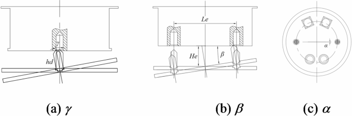
After coarse correction, the maximum radial offset between the active and passive sides is [-Δ1, +Δ1] = [-0.5 mm, + 0.5 mm]. The range of deflection of the passive side around the X-axis is analyzed using the graphical method in positioning analysis coordinate system, as shown in Fig. 12. The limit position occurs when the bottom of the V-groove rotates to the line intersecting the top of the gripping head and the front face. The minimum radius of rotation is rb=150.32 mm, and after rotating at the maximum angle, the resulting chord length is lc=2.728 mm. The maximum clockwise rotation angle (negative) around the X-axis is determined as γ = 1.04° using the following formula.

Rotation angle around the X-axis.
According to the graphical method, the maximum counterclockwise (positive) rotation around the X-axis is no more than 1.04°, i.e., the rotation range around the X-axis is [-γ, +γ] = [-1.04°, + 1.04°]. The rotation angle around the Y-axis is [-β, +β] = [-1.04°, + 1.04°] based on the configuration layout. The rotation angle α around the Z-axis depends on the position of the open section of the V-groove relative to the tapered end of the gripping head. The limit occurs when a point on the V-groove’s open section contacts the intersection of the front and rear edges of the gripping head’s tapered end, with the range given as [-α, +α] = [-0.32°, + 0.32°]. Thus, the maximum positional deviation after coarse correction is presented in Table 6.
Precision calibration design
The fine correction function consists of two stages:
(1) Adjustment of the alignment phase, ensuring that the projection of the guide post’s top corner onto the docking surface consistently aligns with the guide holes. One guide hole is designed as a long U-shaped hole, allowing for equivalent analysis of alignment with a circular guide hole, particularly in terms of radial projection deviation. Based on coarse calibration, the radial translation range of the guiding column relative to the guiding hole is [-0.5 mm, + 0.5 mm]. The guiding column and hole are constructed from titanium alloy and aluminum alloy, respectively, with a friction coefficient of approximately 0.3, resulting in a self-locking angle of \(\:\theta\:>\text{arctan}(f)=16.7^\circ\:\)36,37 The guiding column’s tip angle is restricted to no more than 146.6°, specifically set at 85°. The guide column measures \(\:{\varnothing\:24}_{-0.033}^{0}\) mm, with a tip diameter of approximately 6 mm. The guide hole is Hd=\(\:{{\varnothing}24.2}_{0}^{+0.033}\) mm, with a flare diameter of hd=32 mm, and the center distance between the two semicircles of the long U-shaped holes is 2 mm. The radial offset clearance is \(\:{\rho\:}_{1}=\pm\:\frac{32-6}{2}=13\text{mm}\).
Angle flip illustration.
The angular flip is shown in Fig. 13. Rotation around the X-axis will produce Y- and Z-direction deviations of the column head at the tip of the guide column, where the Z-direction deviation will be actively eliminated when the passive end is captured, so only the resulting Y-direction projection translation is considered.
For rotation around the Y-axis, which in the radial direction causes the X-coordinate point of the guide column to converge towards the origin, the offset is equal to the sum of the X-direction offset of the mounting point of the guide column and the X-direction offset produced by the length of the guide column, with a maximum offset:
When rotating around the Z-axis, the guide column translates in the X-axis and Y-axis directions. The offset at the cylindrical head’s tip corresponds to the offset at the guide column’s mounting point center, with a specified maximum offset of:
Therefore the maximum offset in X and Y direction is:
The maximum offset in both the X and Y directions remains within the radial offset tolerance range ρ1, ensuring that the round head at the tip of the guide column successfully enters the flare of the guide hole.
(2) Precision positioning guide stage: Before the connectors dock, the relative positions of the active and passive sides are adjusted within the required range. The structural design of the guiding column and hole allows for a maximum diameter deviation in the guiding section of \(\:{\rho\:}_{2}=\pm\:\frac{0.2+0.033\times\:2}{2}=\pm\:\text{0.133\,mm}\).
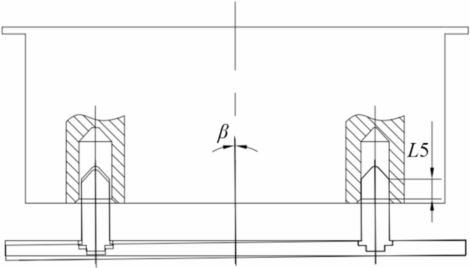
Precision alignment guide illustration.
Assuming the guiding section extends to a depth of L5 within the guiding hole, the relative attitude is adjusted within the connector’s tolerance range, as illustrated in Fig. 14. This adjustment ensures that both the maximum displacement deviation, limited to 1.5 mm, and the attitude deviation, limited to 0.9° for β and γ, are maintained below these thresholds. From this configuration, the minimum length of the guiding section can be determined:
The height of the cylindrical cone angle at the tip of the guide column is as follows:
Based on the connector layout design, the protruding docking surface lengths are 26 mm for the floating liquid connector and 24 mm for the floating electrical connector. Therefore, the minimum length of the guide post is:
Assume the guide column length is L7 = 64 mm. Before the connector makes contact, the guiding and positioning length of the guide column, L5, is approximately 24.9 mm. After positioning, the maximum radial deviation between the active and passive sides is [-0.133 mm, + 0.133 mm]. The maximum angular deflection is:
After fine positioning with the double guide columns and before inserting the connector pair, the maximum deviation range between the active and passive sides is detailed in Table 6. This deviation is within the connector’s tolerance requirements. Under the action of the capture jaw drive, the active side continues to approach the passive side, and the final range of positioning accuracy is detailed in Table 6. As shown in the table below, the positioning requirements at each stage are sequentially executed to ensure automatic centering and precise alignment.
Performance analysis of dual-component calibration positioning
During the docking process and mechanical locking of the mechanism, it is crucial to ensure the proper engagement of the floating electrical and fluid connectors between the active and passive sides. This chapter focuses on analyzing and verifying whether the positioning performance indices meet the alignment requirements of the connectors. To achieve this, a generalized structural deviation calculation method is employed, which can analyze and validate deviation ranges for both planar and spatial structures. This method is versatile, allowing the evaluation of coarse calibration deviation ranges as well as fine calibration deviation ranges. The analysis begins with the derivation of a formula for calculating the floating displacement at any point on the positioning structure within the deviation range, based on the principle of two-pin positioning on one side. This planar formula is then extended to three-dimensional space to account for the complexities of spatial structures. The approach ensures that both planar and spatial deviations can be comprehensively assessed. Subsequently, eight typical working conditions are designed, corresponding to the maximum deviations encountered during coarse calibration, as detailed in Table 6. For each condition, the maximum deviations in the three progressive processes—coarse calibration, precision calibration, and final positioning—are analyzed. These deviations are critical for evaluating the docking mechanism’s ability to achieve the necessary alignment and engagement of the floating connectors.
Theoretical analysis of positioning accuracy of double locating pins
As illustrated in Fig. 15(a), the clearance δ between the positioning pin and hole causes the two components to experience random misalignments that are challenging to replicate and correct38,39,40,41. To analyze the effects of hole-pin float, a coordinate system is set up as shown in Fig. 15b. The locating pin’s coordinate system, XOY(blue), serves as the global coordinate system, while the locating hole’s coordinate system, xoy(red), acts as the local coordinate system.

Double locating pin positioning.
Floating is categorized into main and auxiliary positioning hole pin floating. The floating range of C, at the center of the main positioning hole, forms a circle with a diameter of 2δ. Its floating trajectory is depicted in Fig. 16.

Floating diagram of the primary locating hole.
The positional relationship between the hole center at C and the pin center at O is defined by the coordinates r and θ. The trajectory of C in the XOY is as follows:
Point D, the center of the auxiliary positioning hole, is allowed to float within the Y-axis range λ\(\:\in\:\)(-δ, +δ). This floating motion of D, influenced by the primary positioning hole, involves a composite of translational and rotational movements, as depicted in Fig. 17.

Composite motion of the secondary locating hole center point D.
The trajectory of D, the center of the auxiliary positioning hole, within the XOY is as follows:
In the local coordinate system xoy, the coordinates of any point E(xE,, yE,) remain constant relative to C, despite the floating of the locating hole pin.
Theoretical analysis of the accuracy of dual-component positioning in six dimensions
The described method extends to the six-dimensional accuracy analysis of the dual-component space. As depicted in Fig. 18, the diagram illustrates the mounting relationship between the active and passive sides. Here, {T} and {C} represent the coordinate systems of the docking surfaces for the active sides a and b, respectively, while {G} and {D} denote the altered coordinate systems.

Illustration of the installation relationship between two components.
If GTT represents the position of {T} relative to {G}, then DTC=(GTD)−1 GTTTTC. The center of the passive side’s mounting surface serves as the origin of the world coordinate system, with the distance between the centers of the two docking surfaces being 1642 mm.
Coarse calibration performance analysis
Based on the theory of spatial dual-component positioning accuracy analysis and the results of the maximum position deviation from single-component coarse correction, the position deviation of the active side b relative to the passive side can be seen in Table 7.
The Z-direction displacement deviation of component b, caused by the Y-axis deflection of the winding member a, reaches up to 29.8 mm. Similarly, the Y-direction displacement deviation due to the Z-axis deflection reaches up to 9.17 mm. These deviations should be further constrained by the coarse correction of the capturing jaws of component b. Therefore, subsequent actions involving both components should only proceed after the coarse correction of the capturing jaws for both component a and component b is completed. The maximum positional deviation when the dual components are coarsely corrected together is displayed in Table 8.
Fine positioning performance analysis
Like the coarse positioning analysis, the maximum positional deviation of component b is determined based on the finely corrected maximum deviation of component a. This deviation is detailed in Table 9.
The maximum Z-direction displacement deviation of component b, caused by the Y-axis deflection of winding member a, is up to 1.72 mm, similarly for the Y-direction due to the Z-axis deflection. The coarse correction by component b’s capture jaws limits the Y-direction deviation to less than 0.5 mm, and the Z-direction deviation decreases gradually as the capture jaws close. Consequently, there is no need for a guide column to position component b. The maximum positional deviation of the dual-components after fine positioning is displayed in Table 10.
Static analysis of docking mechanism
This study introduces an extensible application mode for dual docking mechanisms. While a single docking mechanism fulfills the fundamental functions of docking, employing multiple docking mechanisms in combination can enhance the load-bearing capacity. The number of components can be adjusted based on the payload mass. To establish the feasibility of this approach, the mechanical performance of a single component is analyzed first. This ensures the rationality of the single-component design, verifies its mechanical stability, and underscores the significance of optimizing its structural dimensions. Subsequently, the mechanical performance of the dual-component configuration is examined to provide a more comprehensive understanding of the docking mechanism’s overall performance. The layout design for the dual docking mechanism is modeled as a spatially six-fold statically indeterminate structure. Typically, solving such a model involves complex methods such as the displacement method, force method, or energy method. To simplify the analysis, this study leverages the structural symmetry of the mechanism to streamline the solution process. Initially, explicit expressions for three of the forces within the system are derived. For the remaining three forces, their variation trends are analyzed by separately assuming one force to be zero and studying the corresponding changes in the other two forces. This approach provides a clear understanding of the force distribution and variation trends across different positions of the docking mechanism, offering valuable insights for force verification and parameter design.
Static analysis of single components
The maximum load envelope is defined by dimensions ld×hd×wd, with a mass of md and a center of mass height of hOd. The in-orbit state and coordinate system are detailed in Fig. 19.

On-orbit status of a single component and coordinate system definition.
The force at the center of the docking surface of the docking mechanism is depicted in Fig. 20.

Force at the center of the mating surface.
Can be obtained as,
The active side of the track bears the load, and the interaction forces with the passive side are analyzed in Fig. 21. The contact area on the docking surfaces of the active and passive sides is significantly larger than that between the capture claw and the passive side, enhancing the forces experienced during the most demanding working conditions.

Loading at the center of the mating surface and mating surface layout.
From the balance of forces and moments in each direction, we get
Based on the previous equation and structural design, it is evident that additional constraints are implemented to enhance stiffness for the hyperstatic problem42,43. Given the layout’s symmetry, the rack’s approximate centripetal force acts over the origin, with the tangential force perpendicular to it. The tangential forces F7, F8, and F9 collectively exert a torque around the z-axis, which is simplified as follows:
F7 is solely dependent on the angular acceleration and the rack center diameter, given a fixed load. In Fig. 22, the solid line illustrates the relationship between tangential force and rack diameter at an angular acceleration of αwz = 0.2 rad/s2, while the dotted line depicts this at αwz = 0.4 rad/s2. It is evident that as the diameter of the meshing rack’s center increases, the tangential force decreases, with a progressively diminishing rate of change. Considering the specific engineering context, including the installation space and load-bearing requirements of the passive side, and based on the above analysis, the D4 dimension of the passive side should be maximized within the Φ405 × 160 mm range to enhance the structural design. In this design, a preliminary diameter of 300 mm is selected as the baseline for subsequent structural and optimization design.

Trend of tangential force variation on the rack.
Neglecting static friction, this can be simplified as,
Solving for this gives that,
The roles of each force were analyzed using the semi-structural simplification method. Specifically, it was determined that F4 = 0, F5 = 0, and F6 = 0, as outlined below,
To clarify the relationships between each axial force, linear and angular acceleration, three specific working conditions have been established for detailed discussion, as detailed in Table 11. Through the method of controlling variables, the analysis investigates how the docking mechanism’s forces change when the load’s center of mass is subjected to different external linear and angular accelerations. Then, the constraint forces of the docking mechanism can be expressed as a relationship between the linear and angular accelerations.
From the axial force change trend chart in Fig. 23, it is evident that F2>F1>F3. As the diameter at action point D3 increases, F1 and F3 gradually decrease, while F2 increases, though the rate of change diminishes, leading the forces to converge towards equality. Comparative analysis across three conditions reveals that as acceleration and angular acceleration increase, F1 and F3 rise, F2 decreases, and the overall range of force changes narrows. Therefore, in designing and inspecting components subject to axial forces, the responsiveness to acceleration should also be consideration.

Trend of axial force variation.
From the above, it is evident that when one of the forces is zero, the rates of change for the other two centripetal forces decrease as the rack action diameter D4 increases, eventually stabilizing at a fixed value. The impact of changes in angular acceleration on centripetal force is significant. Therefore, it is advisable to maximize the diameter D4, ensuring it exceeds 300 mm, while also considering the corresponding rack strength.
Hydrostatic analysis of double components
The maximum envelope of the dual-component load measures ls×hs×ws, with a mass of ms and a center-of-mass height of hOs. The in-orbit state and the coordinate system are depicted in Fig. 24.

On-orbit status of dual components and coordinate system definition.
It can be obtained that,
The restraining reaction forces on the docking surfaces of the dual components under external loading include:
Based on the hydrostatic analysis results for the active side, the parameters can be simplified through specific substitutions, which include:
Comparing the maximum loads, where the single component’s maximum load is md=2000 kg and the dual-component’s maximum load is ms=4000 kg, both configurations operate with the same acceleration in all directions. This comparison highlights the differences in force magnitude, allowing us to determine the maximum change in the bearing capacity of the docking mechanism.
The maximum variation in load carrying capacity is clearly linked to acceleration. In scenarios where dual components are utilized, the bearing capacity in certain directions can exceed that of the single-component setup. Therefore, mechanical calibration should account for the most demanding operational conditions when dual components are involved.
Validation of test prototypes and mechanical calibration
Design and validation of test prototypes
The docking mechanism test system, illustrated in Fig. 25, includes a profile frame, docking mechanism, pulley, wire rope, and counterweight. The active side is mounted on a six-degree-of-freedom platform, enabling positional deviation adjustments. The passive side is freely suspended, hanging from the frame via the wire rope on a fixed pulley and balanced by a counterweight. This setup allows the passive side to follow the movements of the active side, simulating the follower mode of the manipulator.

Docking mechanism test system.
The positioning accuracy of the docking mechanism was tested using a Leica AT402 laser tracker. The laser tracker comprises an absolute tracker host, a controller, and a red-edge corner prism reflecting sphere. A measuring reference point is selected on the active side of each component, and a measured reference point is selected on the passive side. Initially, the relationship of each datum relative to the center of its respective docking surface is measured. The docking process is then repeated 10 times to measure the positional relationship between the measuring and measured references. The calibration accuracy for the final locking state is detailed in Table 12, showing a maximum positional deviation of 0.12 mm in the X direction, 0.5 mm in the Y direction, 0.07 mm in the Z direction, and a maximum angular deviation of 0.04°. The test results confirm that the calibration accuracy aligns with theoretical predictions and meets the target requirements.
Simulation of the on-orbit impact mechanics environment
During on-orbit operations, large space payloads are docked at designated stations using docking mechanisms. These mechanisms experience impacts during spacecraft docking maneuvers at the space station’s platform, necessitating mechanical calibration. This study’s simulation analysis uses the maximum combined force or moment exerted on the load mounting station under axial and radial conditions as input.
Mechanical verification of single component
The finite element model was developed based on the working condition of a single component mounted on the rail. Beam elements simulate rods, shell elements represent thin plates, and 4- sided or 6-sided solid elements model block structures and other complex geometries not suited for shell elements. Bolted connections are implemented using coupled connections or TIE constraints, with TIE constraints specifically applied to closely contacting parts. Reflecting the actual assembly, 21 screw positions at the passive side were coupled, and forces were applied at these coupling points. The primary materials used are 7075 aluminum alloy and TC4 titanium alloy44,45.
The input conditions for working conditions A (axial docking) and B (radial docking) were derived from simulation results on the XX system platform, as depicted in Fig. 26. The first row shows the resultant force curves for single component a and b under conditions A and B, respectively. The second row displays the corresponding resultant moment curves. Local waveforms for the peak combined forces and moments were extracted and used for calculations across eight localized working conditions, detailed in Appendix A. For Component A, the mean force, torque, impulse, and impulse moment under radial docking conditions are larger, indicating that the energy change due to radial impact is more significant than that due to axial docking conditions. For Component B, the results differ. The mean force and impulse under radial docking conditions are larger, while the mean torque and impulse moment under axial docking conditions are greater.

Overall impact load under two conditions.

Single component a is loaded near the resultant force peak in condition A.
The deformation and stresses of a single component under the peak loading from the combined forces of component a in condition A are depicted in Fig. 27. Additionally, the output results for various conditions are detailed in Table 13.
From the analysis, the maximum displacement under condition A for component a’s combined moment peak loading is 0.5888 mm, located at the camera installation point. This displacement does not compromise load-bearing performance. The maximum stress, approximately 186.7 MPa, occurs under the peak loading condition for component b’s combined moment in condition A. This stress, located at the bearing cylinder, remains below the 455 MPa yield stress of 7075 aluminum alloy, resulting in a safety coefficient of 2.43. Deformation and stress are primarily concentrated in the bearing cylinder, capture claw, target adapter plate, and the flange of the passive side. Design optimization should therefore prioritize strengthening these critical areas.
Mechanical verification of dual-components
The finite element modeling approach for the dual assembly mirrors that used for the single assembly. The finite element model is established based on the working conditions of the two components mounted on the rail. Beam elements simulate the rods, shell elements simulate the thin plates, and 4- and 6-sided solids are used to model block structures and other complex geometries that are not suitable for shell elements. Bolted connections are modeled using coupled connections or TIE constraints, with TIE constraints applied to the contact regions. According to the actual installation configuration, 21 screw positions at each passive side are coupled, with loads applied at the coupling points. The materials used are primarily 7075 aluminum alloy and TC4 titanium alloy. The deformation and stress of the dual assembly under the peak loading from the combined force of component a in condition A are depicted in Fig. 28. The output results for other conditions are detailed in Table 14.

Dual components are loaded, with component a near the resultant force peak in condition A.
The analysis indicates that the maximum deformation reaches approximately 0.8442 mm under the peak loading of component a’s combined moment in working condition A. This deformation, occurring at the target adapter plate. Meanwhile, the maximum stress, about 139.3 MPa, arises under the peak loading of component a’s combined moment in working condition B, located within the passive side shell. The associated safety factor is 3.26. Both deformation and stress are primarily concentrated in the target adapter plate, passive side shell, capture claw, and docking surface. Design optimizations should therefore prioritize enhancing the strength of these key areas. In contrast, compared to the results for the single component under each working condition, the maximum deformation increases, while the maximum stress decreases by 25.4% and the safety factor improves by 34.2%. Therefore, the dual-component docking mechanism performs better in terms of force conditions, making it safer and more reliable.
Conclusion
-
(1)
This paper introduces a compact, scalable dual-component docking mechanism for large space loads. The capture jaws feature a parametric design optimized via a genetic algorithm, improving the radial capture range by 4.01% and the axial range by 45.34%. Sensitivity analysis indicates that the inclination angle (θ) of the capture jaws has the greatest impact. A progressive correction and positioning method is developed to address large initial deviations, followed by precise docking of electrical and hydraulic connectors.
-
(2)
For the on-rail configuration, the static mechanics of both single and dual components are analyzed sequentially. Three sets of working condition parameters are proposed, with axial and radial forces calculated and compared across various influencing factors. It is determined that the bearing capacity is primarily influenced by the diameter of the rack mechanism, offering a crucial reference for mechanical calibration.
-
(3)
During prototype testing, the maximum positional deviations of the dual-component system in operation were measured: 0.12 mm in the X direction, 0.5 mm in the Y direction, and 0.07 mm in the Z direction. The maximum angular deviation was 0.04°, all aligning with theoretical predictions. The axial and radial impact conditions of the docking mechanism in orbit were simulated, confirming that the mechanical performance meets the requirements using the finite element method. This validates the approach and provides both theoretical and technical foundations for future development of miniaturized, high-precision docking mechanism for large space loads.
Data availability
All data generated or analysed during this study are included in this published article.
References
Zhang, C. et al. Technical Development of Docking mechanism of Manned Spacecraft in China. Spacecr. Eng. 31(06), 205–212 (2022).
Zhang, B. China Manned Space launch a new Journey. Aerosp. China 8, 8–13 (2021).
Shokrolahi, P. & Ebrahimi, M. An overview of rendezvous and docking space laboratories platforms. Technol. Aerosp. Eng. 8(4), 59–84 (2024).
Li, W. et al. On-orbit service (OOS) of spacecraft: a review of engineering developments. Prog. Aerosp. Sci. 108, 32–120 (2019).
Zhai, G. et al. Development of on-orbit capture technology. Robot 30(5), 467–480 (2008).
Choi, J. et al. Articulated linkage arms based reliable capture device for janitor satellites. Acta Astronaut. 163, 91–99 (2019).
Li, G. & Xu, P. Design and analysis of a deployable grasping mechanism for capturing non-cooperative space targets. Aerosp. Sci. Technol. 106, 106230 (2020).
Zhang, X. et al. Design and analysis of a large tolerance docking mechanism. Acta Astronaut. 221, 121–141 (2024).
Wang, S. & Wang, S. A brief review of the space docking mechanism. 2023 International Conference on Service Robotics (ICoSR) 61–66 (IEEE, 2023).
Xu, C. et al. Optimization of low impact docking mechanism based on integrated joint design and task-oriented force ellipsoid index. Int. J. Mech. Mater. Des. 20(1), 195–208 (2024).
Lewis, J. & Donahoe, S. Space vehicle docking system standardization. J. Space Saf. Eng. 10(2), 127–132 (2023).
Daniels, C. et al. Overview of LIDS Docking and Berthing System Seals. NASA Seal/Secondary Air System Workshop (2006).
Wang, C. et al. The design and dynamic analysis of a lunar lander with semi-active control. Acta Astronaut. 157, 145–156 (2019).
Ueno, H. et al. Berthing Load Analysis between Space Manipulator and Berthing Mechanism during On-orbit Assembly Operation. Proc. of the 9th Int’l Symposium on Artificial Intelligence and Robotics & Automation in Space (2008).
Malyh, D. Modular structuring principle application for develo** various options of the universal space platform layout. Aerosp. MAI J. 30(1), 64–75 (2023).
Golubev, Y. & Yaskevich, A. Hybrid simulation of spacecraft berthing. J. Comput. Syst. Sci. Int. 59, 609–621 (2020).
Malyh, D. et al. Analysis of methods and design elements of docking and un-docking in orbit. Safety in Aviation and Space Technologies: Select Proceedings of the 9th World Congress Aviation in the XXI Century 595–605 (Springer International Publishing, 2021).
Man, W. et al. Research on space target on-orbit capturing methods. International Conference on Mechanical Design 321–343 (Springer Nature Singapore, 2021).
Cook, J. et al. ISS interface mechanisms and their heritage. AIAA SPACE 2011 conference & exposition 7150. (2011).
JEM-EUSO Collaboration et al. The JEM-EUSO mission: an introduction. Exp. Astron. 40, 3–17 (2015).
Zhao, Z. et al. The design and implementation of extravehicular experiments support system for manned spacecrafts. 2023 2nd International Symposium on Aerospace Engineering and Systems (ISAES) 53–58 (IEEE, 2023).
Opromolla, R. et al. Future in-orbit servicing operations in the space traffic management context. Acta Astronaut. 220, 469–477 (2024).
Yin, Z. et al. On-orbit Space Technology Experiment and Verification Project Outlook of China’s Tiangong Space Station 30061 (Science & Technology, 2023).
Wang, X., Zhang, Q. & Wang, W. Design and Application Prospect of China’s Tiangong Space Station30035 (Science & Technology, 2023).
Hu, G. et al. Modular self-reconfigurable spacecraft: development status, key technologies, and application prospect. Acta Astronaut. 207, 240–256 (2023).
Christiansen, S. & Nilson, T. Docking system mechanism utilized on orbital express program. Proceedings of the 39th Aerospace Mechanisms Symposium 207–220 (NASA Marshall Space Flight Center, 2008).
Li, S. & She, Y. Recent advances in contact dynamics and post-capture control for combined spacecraft. Prog. Aerosp. Sci. 120, 100678 (2021).
Kurnell, M. & Sharf, I. Model-based controllers for CubeSat ORU installation: a comparative study. Acta Astronaut. 223, 666–684 (2024).
Gamot, J. et al. Hidden-variables genetic algorithm for variable-size design space optimal layout problems with application to aerospace vehicles. Eng. Appl. Artif. Intell. 121, 105941 (2023).
Visonneau, L., Shimane, Y. & Ho, K. Optimizing multi-spacecraft cislunar space domain awareness systems via hidden-genes genetic algorithm. J. Astronaut. Sci. 70(4), 22 (2023).
Demir, G., Chatterjee, P. & Pamucar, D. Sensitivity analysis in multi-criteria decision making: a state-of-the-art research perspective using bibliometric analysis. Expert Syst. Appl. 237, 121660 (2024).
Huang, M. Y. Sensitivity analysis for the generalization of experimental results. J. R. Stat. Soc. Ser. A qnae012 (2024).
Yang, J. et al. Sensitivity analysis and compensation for tooth surface deviation of spiral bevel gear machine tool. Sci. Rep. 14(1), 22736 (2024).
Fischer, B. R. Mechanical Tolerance Stackup and Analysis (CRC, 2004).
Tang, L. & Xu, X. Study on the calculation of hole/Pin floating deviation for two pins on one side. J. Phys. 2578(1), 012030. (2023).
Yi, Y. et al. A novel assembly tolerance analysis method considering form errors and partial parallel connections. Int. J. Adv. Manuf. Technol. 131(11), 5489–5510 (2024).
Cao, Z. et al. 3D stack-up assembly tolerance analysis for sealing optimization of PEMFCs. Int. J. Hydrog. Energy. 55, 1347–1359 (2024).
Suzuki, S. & Kanada, T. Theoretical analysis of Assembly Variation by Positioning between two parts using a round pin and a Diamond pin. Procedia CIRP. 92, 75–80 (2020).
Liu, C. et al. Image-based visual servoing using a set for multiple pin-in-hole assembly. Assembly Autom. 40(6), 819–831 (2020).
Liu, X. et al. Tolerance analysis of Over-constrained Assembly considering gravity influence: constraints of multiple Planar Hole‐pin‐hole pairs. Math. Probl. Eng. 2018(1), 2039153 (2018).
Shen, F. et al. An automatic assembly control method for peg and hole based on multidimensional micro forces and torques. Int. J. Precis. Eng. Manuf. 20, 1333–1346 (2019).
Nguyen, T. T. et al. Design Optimization of quasi-rectangular Tunnels Based on Hyperstatic Reaction Method and Ensemble Learning (Journal of Rock Mechanics and Geotechnical Engineering, 2024).
Batistini, L. et al. Suspension and tyre loads estimation of an FSAE car: model development and on-track validation. Veh. Syst. Dyn. 1–22 (2024).
Zheng, M. et al. Finite element analysis of bolted joints under torsional loads. Tribol. Int. 201, 110188 (2025).
Dong, S. et al. Finite element analysis and optimization of tractor gearbox body under various kinds of working conditions. Sci. Rep. 12(1), 17386 (2022).
Author information
Authors and Affiliations
Contributions
The authors’ responsibilities were as follows – JLZ : scheme designed; JJL: scheme verified; JLZ, JJL: prototype tested; JLZ, JJL: wrote the paper; CZ: ,revised the paper, KW, CML: had primary responsibility for final content; and all authors: read and approved the final manuscript.
Corresponding authors
Ethics declarations
Competing interests
The authors declare no competing interests.
Additional information
Publisher’s note
Springer Nature remains neutral with regard to jurisdictional claims in published maps and institutional affiliations.
Electronic supplementary material
Below is the link to the electronic supplementary material.
Rights and permissions
Open Access This article is licensed under a Creative Commons Attribution-NonCommercial-NoDerivatives 4.0 International License, which permits any non-commercial use, sharing, distribution and reproduction in any medium or format, as long as you give appropriate credit to the original author(s) and the source, provide a link to the Creative Commons licence, and indicate if you modified the licensed material. You do not have permission under this licence to share adapted material derived from this article or parts of it. The images or other third party material in this article are included in the article’s Creative Commons licence, unless indicated otherwise in a credit line to the material. If material is not included in the article’s Creative Commons licence and your intended use is not permitted by statutory regulation or exceeds the permitted use, you will need to obtain permission directly from the copyright holder. To view a copy of this licence, visit http://creativecommons.org/licenses/by-nc-nd/4.0/.
About this article

Cite this article
Zhang, J., Li, J., Zhao, C. et al. Structural design, accuracy analysis, and mechanical calibration of a small two-component docking mechanism for large loads in space. Sci Rep 15, 4657 (2025). https://doi.org/10.1038/s41598-025-88757-z
Received:
Accepted:
Published:
Version of record:
DOI: https://doi.org/10.1038/s41598-025-88757-z
