
Abstract
We propose and analyze a scheme to enhance optomechanically-induced-transparency (OMIT) based on parity-time-symmetric optomechanical system. Our results predict that an OMIT window which does not exist originally can appear in weak optomechanical coupling and driving system via coupling an auxiliary active cavity with optical gain. This phenomenon is quite different from these reported in previous works in which the gain is considered just to damage OMIT phenomenon even leads to electromagnetically induced absorption or inverted-OMIT. Such enhanced OMIT effects are ascribed to the additional gain which can increase photon number in cavity without reducing effective decay. We also discuss the scheme feasibility by analyzing recent experiment parameters. Our work provide a promising platform for the coherent manipulation and slow light operation, which has potential applications for quantum information processing and quantum optical device.
Introduction
In quantum mechanics and quantum optics, it seems almost inevitable that the quantum system will interact with the environment around it. The dynamics of such an open quantum system can be described by a non-Hermitian Hamiltonian ( ) with complex eigenvalues, which will result in different phenomena from ones in closed quantum system1. Recently, a special class of physical system with a so-called parity-time (
 ) symmetry has attracted great attention2,3,4,5,6,7,8,9. It has been proved that a
  -symmetric non-Hermitian Hamiltonian (
 ) can also have real eigenvalue spectra10,11. This characteristic make open system subject to unitary time evolution like closed system, which causes some environmental damage effects, for example decoherence, can be suppressed effectively. Up to now,
  -symmetric system has shown its extensive application prospects in quantum optics and quantum information processing (QIP), including strengthening optics nonlinearity12,13, enhancing photon blockade14, realizing quantum chaos15, soliton active controlling16,17, and so on.
In addition to theoretical research,  -symmetric Hamiltonian has also been realized experimentally in a variety of physical systems18,19,20,21,22. Among them, a simple and intuitive scheme is to link two coupled cavities with optical gain and loss respectively. Especially in refs 18,20,
  -symmetric region is obviously observed by measuring the eigenfrequencies of supermodes. These progresses of experiments provide a solid platform for exploring the fundamental
  symmetry and corresponding strange phenomena.
Although ( )-symmetry can enhance many quantum optical effects by balancing the loss with extra gain, there still are opposite phenomena in which environmental loss play a positive role. The most typical two of such phenomena are optical cooling23,24,25 and electromagnetically induced transparency (EIT)26,27,28. It is well known that a larger decay rate is necessary whether for EIT in atomic system29 or for optomechanically-induced-transparency (OMIT) in cavity optomechanical system (OMS)26, and a gain is considered just to damage EIT (OMIT) phenomenon even leads to electromagnetically induced absorption (EIA) or inverted-EIT (inverted-OMIT) in previous works30,31. Up until now, enhancing EIT or OMIT still relies on additional coupled dissipation systems32,33,34,35. Correspondingly, the extra dissipation needs strong driving and nonlinear coupling to maintain the interference effect in OMIT, which still remains twofold difficulties because strong driving may lead nonlinear system to instability15 and strong nonlinear coupling is hard to realize in OMS18.
In this paper, we propose and analyze an enhanced optomechanically induced transparency in OMS via coupling an auxiliary active cavity with optical gain. A transparency window can appear in weak optomechanical coupling and driving system, however, similar window can not be obtained in dissipation system unless the driving (or the optomechanical coupling) intensity is magnified roughly 20000 times. This scheme is quite different from ones in existing works because our results show that extra gain can exert positive effect on OMIT phenomenon. Though the conclusion is counter-intuitive, we have analyzed the physical mechanisms of our scheme and explained the reasons of this kind of enhancement. After simulating, we find that absorption and transparency can be of controllable flexibilities by switching the fiber. We believe it can provide a promising platform for the coherent manipulation and slow light operation.
Results
In this part, we present the main results of this work by introducing dynamics analyses and enhanced electromagnetically induced transparency phenomena in parity-time-symmetric optomechanical system. The details of calculation and simulation can be found in METHODS.
Model and dynamics analysis
We consider a typical  -symmetric system for realizing the enhanced OMIT effect (see Fig. 1 for detail) and it is necessary to analyze its dynamics firstly.

(a) Schematic illustration of our enhanced OMIT. Here the  -symmetric OMS consists of a passive OMS coupled to an active cavity with tunnelling strength J. (b) Level diagram of the OMIT in OMS. |m, n〉 denotes the state of m photons and n phonons in the displaced frame. (c) Eigenfrequencies of supermodes as a function of coupling J/(κ + γ).
By setting  , the total Hamiltonian of such a system can be written by increasing oscillator free term and optomechanical interaction on the basis of ordinary cavity Hamiltonian31, i.e.,

The Hamiltonian of the cavity can be written as  , where
  denotes the Hamiltonian of the driving field and correspondingly, the the probe field inside the cavity is described by
  . Here we make a frame rotating via
  and let
  , then the total Hamiltonian of the whole system becomes:

In this expression, 
 and
and 
 are the annihilation (creation) operators of the cavity mode and mechanical mode, respectively. Ωd and εp are the amplitudes of the driving field and the probe field, which are respectively related to the input powers (Pd and Pp) and decay rate (γ), i.e.,
  and
and  .
.  is the detuning between the driving field and cavity field. γ (γm) is the optical (mechanical) decay rate and κ is the gain rate of the active cavity. g0 is the single-photon coupling intensity of the radiation pressure interaction between the passive field and the oscillator. For the convenience of discussion, we define the dimensionless position operator
  and momentum operator
  instead of the phonon operators in Eq. (2). Then the dynamics of such a system can be determined by quantum Langevin equation
  , where
  is an arbitrary optical or mechanical operator and
  is the dissipation term.
Note that both the stability analyses in  -symmetric system and the OMIT phenomena in OMS need to be considered only in the mean value regime15,26. Similarly to previous EIT works in atomic systems, optomechanically induced transparency only deals with the mean response of the system to the probe field without including quantum fluctuation. On the other hand, the non-Hermitian Hamiltonian will be regard as an exact description of an OMS only if the input-bath operators are ignored. Therefore in order to explore the nonlinear dynamics of the system, we employ the semi-classical Langevin equations of motion, that is, set
  in the corresponding quantum Langevin equations. Then the mean values can be obtained by following dynamics equations15,36:

A necessary condition for obtaining an available OMIT phenomenon is that there should exist an asymptotic steady state and the corresponding system will keep the state for a long evolution time. As we all know, the probe field in OMIT typically has a small amplitude and it would not have an influence on the stability of the system. Therefore, here we firstly ignore the term  in Eq. (3) for a more simple stability analysis and the stability or stochastic property of the system is characterized by the Jacobian matrix

which can be obtained by linearizing Eq. (3) under the base vector 
 . Here we neglect the optomechanical interaction in Eq. (4) under the condition of weak-coupling regime
  . In this case, the eigenvalues of this Jacobian matrix can be easily solved as

The real parts of above eigenvalues are also known as the Lyapunov exponents of this nonlinear dynamical system37,38,39. Whether the system is stable or not can be judged by comparing the largest Lyapunov exponent with zero38,40. Equation (5) implies that if J > (κ + γ)/4, the second terms in λ3,4,5,6 will be pure imaginary numbers. The real parts of these eigenvalues will not change with the parameter J and the corresponding Lyapunov exponents are Ly1,2 = −γm/4 and Lγ3,4,5,6 = (κ − γ)/4. If the decay and gain rates are in the regime κ < γ, all Lyapunov exponents of this system will be negative, which can ensure that the mean value trajectories will tend to a fixed point in phase space. On the contrary, the second terms in λ3,4,5,6 will present non-zero real parts if J < (κ + γ)/4, which causes positive Lyapunov exponents. In the unstable system, neglected terms g0Re[a1], g0Im[a1] and g0x in Jacobian matrix will continue to be amplified, and this phenomenon is equivalent to enlarging the nonlinear coupling coefficient and the system will become more unstable in this case.
Here we give the feasibility analysis of our parameters used in above discussions. The dimensionless parameters are in accord with recent microcavity experiments, that is, ωc = 190 THz and ωm/2π = 23.4 MHz. The Q-factor of passive cavity is  corresponding to γ ~ 6.33 MHz and γ/2π ~ 1 MHz. The optomechanical interaction intensity in this cavity is g0 = 7.4 × 10⁻⁵γ and corresponding oscillator decay is γm/2π ~ 38 kHz owing to Qm ~ 2Qc/10518,19,20. The driving and probe powers are Pd ~ 8 pW and Pp ~ 0.08 pW, respectively. In addition, a small gain rate and fiber coupling (J, κ < γ) are also easy to be achieved in experiments41,42. After adopting these parameters, we select ωm = 1 as an unit to nondimensionalize the other parameters, i.e., γ = 1/23.4, γm = 0.038γ and Ωd = 10γ. It can been found that the parameters used in our simulations are similar with ones in previous works15,30. In Fig. 2, we verify above discussions by numerically calculating the oscillator evolutions and the largest Lyapunov exponents. Figure 2(a) shows that the critical point of the system stability is at J = (κ + γ)/4. When J is increased to be greater than the critical point, a significant asymptotic steady state emerges in this system (see Fig. 2(b)). On the other hand, decreasing J pushes the system to chaotic motion (see Fig. 2(c)). Since the nonlinear term is enlarged in this case, there exists a deviation for the largest Lyapunov exponents between the numerical solution and the corresponding analytical solution. However, the analytical largest Lyapunov exponent is accurate when the system is stable.

(a) Analytical (blue) and numerical (red) Lyapunov exponents as a function of coupling J/(κ + γ). (b,c) Evolutions of dimensionless mechanical displacement x in  -SP and
  -BP, respectively. The dimensionless parameters in this simulation are: Δc = ωm = 1, γ = 1/23.4 = 0.043, γm = 0.038γ = 1.652 × 10⁻³, g0 = 7.4 × 10⁻⁵γ = 3.217 × 10⁻⁶,
  and
and  . In (b,c) J/(γ + κ) is taken as 1 and 0.2, respectively.
After ignoring the oscillator dissipation, we can make an inversion based on Eq. (3) and obtain following non-Hermitian Hamiltonian

to describe this  -symmetric system. By diagonalizing the non-Hermitian Hamiltonian, one can easily find that J = (κ + γ)/4 is also the exceptional point (EP) of the transition from the
  -symmetric phase (
 -SP) to
  -symmetry breaking phase (
 -BP). Therefore, we emphasize such a conclusion that the system will always be stable in
  -SP. This is the essential prerequisite for enhancing OMIT by using
  -symmetric OMS.
Enhanced optomechanically induced transparency
The steady-state solution of Eq. (3) can be expanded to contain many Fourier components. In the limit of weak probe field, the high order terms of εp are neglected in our work and each operator will have the following form26,43:

under the condition of t → ∞. Substituting Eq. (7) into Eq. (3) and ignoring these terms containing  ,
,  and |εp|2, we can respectively gain the zero-order and first-order steady-state equations (see METHODS for detail). The steady-state solutions can be given finally by:

and

in which the undefined variables are:

In order to obtain the OMIT behavior in this model, the output field should be solved to illustrate its response. Based on the input-output relation, the output field can be got by

We also extend the output field εout(t) in the form of

and the following relations can be achieved by substituting Eq. (12) into Eq. (11):

Observing OMIT phenomenon requires us to specifically focus on the response of the cavity optomechanical system to the probe field in the presence of the coupling field. In Eq. (12), the component of the output field oscillating at the probe frequency corresponds to the term +εout, and one can intuitively find from Eq. (13) that +εout does not vary with the coupling field. Similarly to previous works, we concentrate on the behavior of +a1 and define  for the convenience of discussion. The relevant absorption and dispersion theories inspire us that real part and imagery part of χ respectively represent the behaviors of absorption and dispersion26.
In Fig. 3(a,b), we first exhibit the enhancement effect on the OMIT phenomenon in this  -symmetric OMS (blue dashed line). The real part and imagery part of χ show an obvious transparent window emerges at the frequency
  . This OMIT phenomenon can still appear even in the weak driving and weak optomechanical coupling regimes, which is quite different from the OMIT in the normal passive system. When J = 0, the
  -symmetric OMS returns to a normal passive system and the gain rate κ no longer exist and the system only has decay rates γ and γm. Figure 3 illustrates that the absorption and dispersion properties perform like a light falling on a normal medium and there are not any transparent windows in this case since the driving and coupling are both too weak. The comparisons between blue line and red line in Fig. 3 show OMIT phenomenon is enhanced by the
  -symmetric system. The insets in Fig. 3(a,b) show that such an enhancement effect in fact can be carried out in a wide range of parameters. As a criterion of enhanced OMIT, the depth of transparent window is almost unchanged even though the γ and γm are both enlarged. What is influenced by dissipation is the width of transparent window and it is widened significantly when γ and γm are increased, implying that the enhancement effect discussed in our work is a general conclusion to a certain extent, i.e., it does not require that γ and γm are both extremely small. It can be known from Fig. 4, that OMIT phenomenon can not be obtained in normal passive system unless there exists very strong optical driving or optomechanical coupling. In Fig. 4(a), we show that, in order to obtain OMIT, increasing the driving intensity or coupling intensity is equivalent in this system and Fig. 4(b) indicates that Ωdg0 is required to be amplified 15000 times for achieving a similar OMIT phenomenon Re(χ) → 0. Based on the above discussions, one can conclude that a
  -symmetric OMS can indeed enhance the OMIT phenomenon.

(a,b) Respectively correspond to the real and imaginary parts of χ. In both figures, the blue dash lines denote the χ in  -symmetric OMS (
 ) and red solid lines are χ in normal passive system (J = 0). In this simulation, the gain rate is set as weak intensity κ/γ = 10−4 and other parameters are the same with Fig. 2. The insets in (a,b) describe the changes of Reχ and Imχ with enlarged cavity and oscillator dissipations. Here the blue lines are of the same parameters with ones in main figures and the green lines refer to the case we amplify the cavity dissipation 2 times and oscillator dissipation 20 times (γ = 2/23.4 and γm = 0.38γ), and the black lines denote the both dissipations are amplified 4 and 40 times, respectively (γ = 4/23.4 and γm = 0.38γ).

(a) Real part of χ at δ = ωm as functions of magnified driving  and coupling intensity g. (b) Real part of χ at δ = ωm as function of
  . The inset in (b) shows the absorption spectra under
  (blue), 10000 (red) and 15000 (green), respectively. The parameters here are the same with Fig. 3.
Further more, we introduce an optomechanically induced amplification phenomenon in this enhanced OMIT, that is, the probe field may be amplified by the active cavity if we increase its gain rate κ. We find that the amplification is selective, meaning that it can be realized in this system only when the probe field satisfies ωp − ωd = ωm. To describe this property, we consider the variable  and plot it in Fig. 5. In Eq. (11), we have defined the output corresponding to the probe field is of the amplitude
  . Therefore,
  can be regard as a magnification since it is an amplitude ratio between the response and probe field. In normal OMIT phenomenon, the maximum response amplitude should be μ = 1 due to the conservation of energy. Physically, this case means all probe fields are exported without any dispersion. However, the existence of the active cavity allows response field to carry more energy than the probe field. In Fig. 5(a), one can observe significant amplification effect with the increasing of κ. In particular, the probe field will be doubled at κ = 0.1. It is worth noting that amplified probe (response) field is still a small quantity compared to the driving field. Thus, the dynamics analyses in Eqs (4)~(13) are still accurate. The inset in Fig. 5(a) shows that this amplification phenomenon only exists at the transparent frequency δ = ωm. Correspondingly, the dispersion spectra (see Fig. 5(b) and its inset) illustrate that there are not any dispersion effects in this case. The above two properties clarify the reason why we think this amplification is selective. Moreover, the insets in Fig. 5 show the absorption and dispersion spectra are similar with these in normal OMIT phenomena except for negative Re(χ). Especially, the widths of the transparency windows almost keep unchanged. Therefore, this enhanced OMIT can be directly used in some schemes of OMIT applications without changing other properties.

(a,b) Respectively correspond to the real and imaginary parts of μ. The insets in (a,b) show the absorption and dispersion spectra under κ = 0.01 (green), κ = 0.05 (red) and κ = 0.1 (blue). The parameters here are the same with Fig. 3.
Discussion
Transformation between inverted-OMIT and OMIT
In the above section, we have already shown a transparent window (Re(χ) → 0) and Im(χ) → 0) will appear after we add an extra gain to keep the system in  SP. A natural question is what this transparent window corresponds to, an ordinary OMIT or an inverted-OMIT. The achieved answer is that
  symmetry can enhance both OMIT and inverted-OMIT. The inverted-OMIT in
  -symmetric OMS has been reported in ref. 30 recently. The OMIT effect, never being observed in gain systems, can also be enhanced under certain parameters. In order to show our conclusions intuitively, we calculate the transmission rate
  , i.e., the square of amplitude ratio between the output field and input field amplitudes, to distinguish OMIT or inverted-OMIT30. Using the input-output relationship in Eq. (13), the transmission rate can be simplified as

due to narrow bandwidth driving and detecting fields. Generally speaking, a typical OMIT-like transmission rate corresponds to such a one with a transparency window and two sideband dips in frequency domain. It takes on, however, a significant difference with inverted-OMIT phenomenon in which corresponding transmission rate exhibits a transmission dip and two sideband peaks30,44,45,46.
It can be known from Fig. 6(a) that under some certain parameters, one can make the system switch between transparency and inverted transparency by only adjusting the coupling intensity J of fiber and the gain κ on the auxiliary cavity. The transmission rate η takes on a significant decline at δ = ωm when J = 0. Physically, this means that the optomechanical system corresponds to an absorption process on the probe field. When the fiber is connected (J ≠ 0) and its coupling is adjusted to the appropriate interaction strength, a transmission window with η ~ 1 appears at δ = ωm with two sideband dips. By setting different J and κ, an inverted-OMIT phenomenon can be also observed in our system, meaning that we can achieve both slow light and fast light operations in such a system and the absorption and transparency can be of controllable flexibilities by switching the fiber. The inset in Fig. 6(a) shows that the optomechanically induced amplification phenomenon exhibits similar transmission rate curve with the OMIT phenomenon. The only difference between optomechanically induced amplification and OMIT is that η(ω) of the former will be greater than 1 because the probe field is amplified by the auxiliary cavity.

(a) Comparison of transmission rates corresponding respectively to absorption process (red), OMIT (blue), inverted-OMIT (green) and inverted-OMIT in ref. 26. Here we set g = 7.4 × 10⁻⁴γ, γm = 0.38γ and Ωd = 5000γ. The absorption, OMIT and inverted-OMIT respectively correspond to J = 0, 0.2501(γ + κ) and (γ + κ); κ = 0, 10−4γ and 0.05γ. The inset in (a) is the comparison of transmission rates corresponding to OMIT (blue, κ = 10−4γ) and optomechanically induced amplification (red, κ = 10−2γ). (b) Comparison of transmission rates corresponding to γ = 1/23 (blue), γ = 2/23 (green) and γ = 4/23 (black) with γm = 0.38γ. Here the other parameters are the same with the Fig. 2.
In Fig. 6(b), we show that the OMIT-like transmission rate can also appear even if the γ and γm are both enlarged, which is a similar conclusion with Fig. 3. In particular, the transparent window will not be affected with the increased dissipation and η(ω) ~ 1 is always satisfied. Relatively, the deep two sideband dips become shallow and the width of the transparent window will be broadened in this case.
Physical mechanism of enhancing OMIT
Now we discuss the physical mechanism why parity-time-symmetric system can enhance OMIT by an extra gain. The underlying physics of OMIT is formally similar to that of ordinary EIT in atomic system and we know that emerging traditional EIT in Λ-type atom system requires three necessary conditions. Analogizing optomechanically induced transparency to EIT in atomic systems, Huang and Agarwal in ref. 47, discussed this relation and sketched three conditions for engendering OMIT, that is,
-
i
Driving frequency is set in the red sideband, that is,
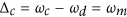 .
. -
ii
Optical field loss needs to be much greater than oscillator dissipation, i.e.,
 .
. -
iii
Steady state of oscillator displacement is not zero, i.e.,
 .
.
 .
. .
. .
.Intuitively, conditions 2 and 3 are contradictory in a normal dissipative optomechanical system because the condition  requires a large optical field decay, which will result in a decrease of the photon number in the cavity. When the photon number is reduced, the oscillator displacement will approach to equilibrium position and the condition iii is violated in this case. In order to solve this contradiction, strong driving is needed in previous works to ensure more photons preserved in the cavity and strong optomechanical interaction is demanded for a nonvanishing oscillator displacement x. That is why Fig. 4 shows the OMIT effect appears only with strong driving and optomechanical interaction.
In  -symmetric OMS, we find that the gain can increase the photon number. Under some certain parameters, however, this gain almost does not reduce the effective dissipation of the system, which ensures the condition iii is also well satisfied. In other words, the contradictory OMIT conditions can be well met simultaneously in
  -symmetric OMS even with weak optomechanical coupling and driving, and it is the reason for the positive effect of
  -symmetric OMS on OMIT.
Now we verify the above analyses in mathematics and let us re-examine the steady state solution in Eq. (8). The oscillator displacement depends on the photon number in the cavity, which jointly affect the OMIT phenomenon via parameter β (see Eq. (9)). For the quantitative interpretation, we simplify β as

by substituting Eq. (10) into Eq. (8) and neglecting Δ′. In Eq. (15), we find that β depends on the product rather than independent driving and coupling intensities, and it is the reason why increasing driving intensity or coupling intensity is equivalent and hyperbolic contour appears in Fig. 4. More importantly, it can be known from Eq. (15) that the extra auxiliary cavity can provide frequency and decay corrections in the expression of β, that is,  and
and  , where
  . If κ is positive, i.e., a gain effect on the auxiliary cavity, both Δeff and Γeff will be reduced and correspondingly, β will be amplified because Δeff and Γeff appear in the denominator of Eq. (15).
Here we emphasize that the corrections of frequency (Δeff) and decay (Γeff) described above are only applicable to the discussion of β. In addition to the impact of β, the extra auxiliary cavity can also change dynamics characteristics of the system. As shown in Fig. 1(c), the cavity mode will take place a model splitting  in the
  -SP regime5,15. If we set J to be very close to the EP (J ~ 0.2501(κ + γ)), two splitting models will degenerate again with an effective decay γeff = γ − κ (see effective energy level diagram in Fig. 1(b)). A small κ allows us to ignore it, which causes the effective energy level decay is not affected by the auxiliary cavity. Therefore, the condition
  can still be well satisfied.
However, if the auxiliary cavity is also a dissipative cavity without gain, the auxiliary cavity (or other coupled quantum systems) can not always guarantee to increase β because Γeff will increase when κ is negative. Though γeff = γ + |κ| is increased in this case, it can not always guarantee for a positive effect on OMIT. This is the reason why our scheme is superior to other schemes which use passive quantum system to enhance OMIT32,33,34,35.
In summary, we have proposed a theoretical scheme to enhance the OMIT phenomenon in  -symmetric OMS. By calculating absorption (dispersion) spectrum and transmission rate, we have achieved an obvious OMIT window with experimentally accessible parameter values. In contrast to the single passive nonlinear OMS or coupled passive systems, our results illustrate that Re(χ) ~ 0 and Im(χ) ~ 0 are easy to be satisfied even though both driving and nonlinear coupling are extremely weak. This enhancement effect is due to the additional gain. Specifically, a special physical mechanism ensures that the photon number in cavity is increased without reducing effective decay, and this is the key difference between our scheme and previous works in which the gain is considered just to damage OMIT phenomenon. We have found that this scheme allows us to flexibly control absorption and transparency by switching the fiber. Moreover, the probe field can also exhibit an electromagnetically induced amplification effect with the increasing gain rate. We thus believe the scheme proposed here may provide a promising choice for the unachievable strong nonlinear coupling in quantum optical devices, which is of potential applications for coherent manipulation, slow light operation and other utilizations in QIP 48 .
Methods
Derivation of the absorption and dispersion spectra
As we have discussed in RESULTS, the steady-state solution of Eq. (3) can be expanded to the following form:

under the condition of t → ∞, and the relation

can be intuitively obtained. Substituting Eq. (17) into Eq. (3), the dynamics equations of systemic mean values become:

and

after ignoring these terms which contain  ,
,  and |εp|2. Here Eqs 18 and 19 correspond respectively to first-order and second-order steady states. Therefore, Eq. 19 can be further simplified as:

Based on Eqs 18 and 20, the steady-state solutions can be given finally by:

and

which are exactly the same with Eqs 8 and 9 in Results.
Additional Information
How to cite this article: Li, W. et al. Parity-time-symmetry enhanced optomechanically-induced-transparency. Sci. Rep. 6, 31095; doi: 10.1038/srep31095 (2016).
References
C. M. Bender . “Making sense of non-Hermitian Hamiltonians”. Rep. Prog. Phys. 70, 947–1018 (2007).
P. Sendy et al. “Parity-time symmetric coupled microresonators with a dispersive gain/loss”. Opt. Express 23, 11493–11507 (2015).
Z. Chen, H. Wang, B. Luo & H. Guo . “Parity-time symmetric Bragg structure in atomic vapor”. Opt. Express 22, 25120–25127 (2014).
S. Nixon, Yi Zhu & J. Yang . “Nonlinear dynamics of wave packets in parity-time-symmetric optical lattices near the phase transition point”. Opt. Lett. 37, 4874–4876 (2012).
H. Jing, S. K. Özdemir, X. Y. Lü, J. Zhang, L. Yang & F. Nori . “ -symmetric phonon laser”. Phys. Rev. Lett. 113, 053604 (2014).
S. V. Dmitriev, A. A. Sukhorukov & Y. S. Kivshar . “Binary parity-time-symmetric nonlinear lattices with balanced gain and loss”. Opt. Lett. 35, 2976–8 (2010).
X. W. Xu, Y. X. Liu, C. P. Sun & Y. Li . “Mechanical PT symmetry in coupled optomechanical systems”. Phys. Rev. A 92, 013852 (2015).
S. L. Chen, G. Y. Chen & Y. N. Chen . “Increase of entanglement by local PT-symmetric operations”. Phys. Rev. A 90, 054301 (2014).
Z. Ahmed, J. A. Nathan & D. Ghosh . “Transparency of the complex PT-symmetric potentials for coherent injection”. Phys. Lett. A 380, 562 (2016).
C. M. Bender & S. Boettcher . “Real spectra in non-Hermitian Hamiltonians having PT symmetry”. Phys. Rev. Lett. 80, 5243 (1998).
C. M. Bender, D. C. Brody & H. F. Jones . “Complex extension of quantum mechanicsy”. Phys. Rev. Lett. 89, 270401 (2002).
J. Li, X. Zhan, C. Ding, D. Zhang & Y. Wu . “Enhanced nonlinear optics in coupled optical microcavities with an unbroken and broken parity-time symmetry”. Phys. Rev. A 92, 043830 (2015).
S. K. Gupta & A. K. Sarma . “Peregrine rogue wave dynamics in the continuous nonlinear Schrödinger system with parity-time symmetric Kerr nonlinearity”. Commun. Nonlinear Sci.Numer. Simulat. 36, 141–147 (2016).
J. Li, R. Yu & Y. Wu . “Proposal for enhanced photon blockade in parity-time-symmetric coupled microcavities”. Phys. Rev. A 92, 053837 (2015).
X. Y. Lü, H. Jing, J. Y. Ma & Y. Wu . “ -symmetry-breaking chaos in optomechanics”. Phys. Rev. Lett. 114, 253601 (2015).
R. Driben & B. A. Malomedu . “Stability of solitons in parity-time-symmetric couplers”. Opt. Lett. 36, 4323–4325 (2011).
F. Nazari et al. “Optical isolation via -symmetric nonlinear Fano resonances”. Opt. Express 22, 9574–9584 (2014).
B. Peng et al. “Parity-time-symmetric whispering-gallery microcavities”. Nat. Phys. 10, 394–398 (2014).
A. Regensburger et al. “Parity-time synthetic photonic lattices”. Nature 488, 167–171 (2012).
L. Chang et al. “Parity-time symmetry and variable optical isolation in active-passive-coupled microresonators”. Nat. Photon. 8, 524–529 (2014).
L. Feng et al. “Nonreciprocal light propagation in a silicon photonic circuit”. Science 333, 729–733 (2011).
B. Peng et al. “Loss-induced suppression and revival of lasing”. Science 346, 328–332 (2014).
Y. C. Liu, Y. F. Xiao, X. Luan & C. W. Wong . “Dynamic dissipative cooling of a mechanical resonator in strong coupling optomechanics”. Phys. Rev. Lett. 110, 153606 (2013).
S. Zhang et al. “Ground state cooling of an optomechanical resonator assisted by a Λ-type atom”. Opt. Express 22, 28118–28131 (2014).
W. Nie, A. Chen & Y. Lan . “Cooling mechanical motion via vacuum effect of an ensemble of quantum emitters”. Opt. Express 23, 30970–84 (2015).
G. S. Agarwal & S. Huang . “Electromagnetically induced transparency in mechanical effects of light”. Phys. Rev. A 81, 041803(R) (2010).
J. Ma et al. “Optomechanically induced transparency in the mechanical-mode splitting regime”. Opt. Lett. 39, 4180–4183 (2014).
R. Thomas, C. Kupchak, G. S. Agarwal & A. I. Lvovsky . “Observation of electromagnetically induced transparency in evanescent fields”. Opt. Express 21, 6880–6888 (2013).
T. Y. Abi-Salloum . “Electromagnetically induced transparency and Autler-Townes splitting: Two similar but distinct phenomena in two categories of three-level atomic systems”. Phys. Rev. A 81, 053836 (2010).
H. Jing et al. “Optomechanically-induced transparency in parity-time-symmetric microresonators”. Sci. Rep. 5, 9663 (2015).
M. Aspelmeyer, T. J. Kippenberg & F. Marquardt . “Cavity optomechanics”. Rev. Mod. Phys. 86, 1391–1452 (2014).
Y. Xiao, Y. F. Yu & Z. M. Zhang . “Controllable optomechanically induced transparency and ponderomotive squeezing in an optomechanical system assisted by an atomic ensemble”. Opt. Express 22, 17979–17989 (2014).
Y. Turek, Y. Li & C. P. Sun . “Electromagnetically-induced-transparency–like phenomenon with two atomic ensembles in a cavity”. Phys. Rev. A 88, 053827 (2013).
Y. Han, J. Cheng & L. Zhou . “Electromagnetically induced transparency in a cavity optomechanical system with an atomic medium”. J. Phys. B. At. Mol. Opt. Phys. 44, 165505–165509 (2011).
Y. Chang, T. Shi, Y. X Liu, C. P. Sun & F. Nori . “Multistability of electromagnetically induced transparency in atom-assisted optomechanical cavities”. Phys. Rev. A 83, 063826 (2011).
A. Farace & V. Giovannetti . “Enhancing quantum effects via periodic modulations in optomechanical systems”. Phys. Rev. A 86, 013820 (2012).
Z. Liu, Y. C. Lai & M. A. Matas . “Universal scaling of Lyapunov exponents in coupled chaotic oscillators”. Phys. Rev. E 67, 045203(R) (2003).
L. Lü et al. “The signal synchronization transmission among uncertain discrete networks with different nodes”. Nonlinear Dyn. 81, 801–809 (2015).
L. Lü et al. “Spatiotemporal chaos synchronization of an uncertain network based on sliding mode control”. Chin. Phys. B 21, 100507–5 (2012).
W. L. Li, C. Li & H. S. Song . “Quantum parameter identification for a chaotic atom ensemble system”. Phys. Lett. A 380, 672–677 (2016).
M. Eichenfield et al. “A picogram- and nanometre-scale photonic-crystal optomechanical cavity”. Nat. Lett. 459, 550–555 (2009).
M. Eichenfield et al. “Optomechanical crystals”. Nat. Lett. 462, 78–82 (2009).
H. Wang, H. C. Sun, J. Zhang & Y. X. Liu . “Transparency and amplification in a hybrid system of the mechanical resonator and circuit QED”. Sci. China-Phys. Mech. Astron. 55, 2264–2272 (2012).
T. Oishi & M. Tomita . “Inverted coupled-resonator-induced transparency”. Phys. Rev. A 88, 013813 (2013).
J. Kou et al. “EIT-assisted large cross-Kerr nonlinearity in a four-level inverted-Y atomic system”. J. Opt. Soc. Am. B 27, 2035–2039 (2010).
P. C. Ma, J. Q. Zhang, M. Feng & Z. M. Zhang . “Bidirectional and tunable single-photons multi-channel quantum router between microwave and optical light”. arXiv:1410.4371v1 (2014).
S. Huang & G. S. Agarwal . “Electromagnetically induced transparency from two-phonon processes in quadratically coupled membranes”. Phys. Rev. A 83, 023823 (2011).
J. Zhang, G. Hernandez & Y. Zhu . “Copropagating superluminal and slow light manifested by electromagnetically assisted nonlinear optical processes”. Opt. Lett. 31, 2598–2600 (2006).
Acknowledgements
All authors thank Dr. Jiong Cheng, Dr. Wenzhao Zhang and Dr. Yang Zhang for the useful discussion. This research was supported by the National Natural Science Foundation of China (Grant No 11175033, No 11574041 and No 11447135) and the Fundamental Research Funds for the Central Universities (DUT13LK05).
Author information
Authors and Affiliations
Contributions
W.L. and H.S. proposed the basic idea of enhanced optomechanically induced transparency in parity-time-symmetric optomechanical system; Y.J. and C.L. analyzed the system stability corresponding to Figure 2; W.L. and H.S. wrote the main manuscript text and all authors have given approval to the final version of the manuscript.
Corresponding authors
Ethics declarations
Competing interests
The authors declare no competing financial interests.
Rights and permissions
This work is licensed under a Creative Commons Attribution 4.0 International License. The images or other third party material in this article are included in the article’s Creative Commons license, unless indicated otherwise in the credit line; if the material is not included under the Creative Commons license, users will need to obtain permission from the license holder to reproduce the material. To view a copy of this license, visit http://creativecommons.org/licenses/by/4.0/
About this article

Cite this article
Li, W., Jiang, Y., Li, C. et al. Parity-time-symmetry enhanced optomechanically-induced-transparency. Sci Rep 6, 31095 (2016). https://doi.org/10.1038/srep31095
Received:
Accepted:
Published:
DOI: https://doi.org/10.1038/srep31095
This article is cited by
-
Controllable transparency and slow–fast light in an optomechanical system with a triple quantum well
Optical and Quantum Electronics (2024)
-
Perfect optomechanically induced transparency in two-cavity optomechanics
Frontiers of Physics (2023)
-
Topological nonlinear optics with spin-orbit coupled Bose-Einstein condensate in cavity
npj Quantum Information (2022)
-
Study on exponential synchronisation between the time-delay spatiotemporal network and the target system
Pramana (2021)
-
Enhanced optomechanically induced transparency via atomic ensemble in optomechanical system
Quantum Information Processing (2021)
