
Abstract
In traditional infusion processes, issues such as untimely medication replacement and patients’ difficulty in continuously monitoring their medication levels are prevalent. This study presents the design of a smart infusion automatic medication replacement device aimed at automating infusion management through three key modules: high-precision liquid level monitoring, automated medication replacement, and a smart control system. By monitoring liquid levels in real time, the system eliminates the need for patients to constantly check their medication levels, accurately controlling the amount of medication dispensed and transmitting monitoring signals within safe thresholds. The rotational medication replacement mechanism stores and precisely replaces medicine bottles, optimizing usage and minimizing waste. Automated settings for liquid level monitoring and the plug-and-push system replace the need for manual assessment of medication completion and input quality, ensuring consistent dosage and high-quality delivery. The rotational mechanism also reduces the time needed for refilling and decreases the labor intensity for healthcare providers. A stabilization and calibration mechanism ensures bottles remain centered, preventing issues with internal pressure changes and loosening of the piercing tool. By replacing repetitive manual adjustments with automated processes, healthcare professionals can focus more on patient care rather than the cumbersome medication replacement procedures. The smart infusion automatic medication replacement device enhances the quality of infusion therapy for patients and alleviates the repetitive workload of medical staff.
Introduction
Intravenous infusion therapy is a fundamental aspect of modern medical practice, widely used across various clinical settings1,2,3. However, traditional methods for infusion and medication replacement have several limitations, including inconsistent manual monitoring4, delays in medication bottle replacement5, and the potential for human errors6. During prolonged infusion periods, healthcare providers and patients must continuously monitor the infusion status, which increases the workload for clinicians due to frequent medication changes and poses safety risks if patients forget to replace medications during rest periods7,8,9,10.
Smart infusion pumps have shown exceptional performance in significantly reducing medication errors by employing real-time monitoring and automatic correction functions, particularly in intensive care units11. Studies indicate that the implementation of smart infusion pumps in pediatric intensive care units notably decreases medication dosage errors12. In terms of automation and precision in drug delivery, smart pumps enable the automatic replacement of vasoactive drugs, greatly enhancing the continuity and accuracy of infusions13. Furthermore, the development of Internet of Things (IoT)-driven automated infusion systems promises advanced monitoring and alert capabilities in the future14,15,16.
Building further on these smart technologies, recent studies have explored the integration of the IoT into infusion systems, with research by Bai, Wang, and Cao focusing on infusion control systems to improve orthopedic nursing tasks17. Liu, Jiang, and Wang expanded on this by applying IoT technology to manage implantable intravenous ports for pediatric oncology patients, illustrating its efficacy in complex medical environments18. The potential for smart automated drug administration systems is being advocated by researchers like Sharma, Singh, and Gaur, while Wang’s group introduced an infrared infusion monitor to improve monitoring accuracy through sophisticated data processing techniques19,20.
Recent advancements in medical technology have led to significant improvements in smart infusion systems, focusing on enhancing patient safety, accuracy, and efficiency—key elements in the development of smart drug management devices21,22,23. Initial efforts, such as those by Oros and colleagues, introduced smart infusion systems that utilize advanced algorithms to refine drug delivery precision, laying the groundwork for smart dosing strategies24. Additionally, developments in image-processing-based monitoring offer real-time solutions for adjusting infusion rates, supporting automated drug management systems25,26. In critical care settings, smart technology has been effective in intercepting errors, highlighting the importance of robust control algorithms for precision and error prevention27. Ergonomic design improvements further enhance usability, reducing operator-related errors28. Moreover, machine learning models can predict infusion rates in anesthesia, showcasing the potential of AI-enhanced smart devices for personalized drug delivery29,30,31.
Efforts to make healthcare innovations more accessible are evident in the work of Jannah and colleagues, who developed an affordable infusion device analyzer based on Arduino, suitable for resource-limited settings32,33,34. Meanwhile, Bosque’s development of an alarm algorithm with a nanotechnology-enabled sensor aims to predict and prevent infusion failures, highlighting advancements in early error detection, particularly in neonatal care35,36,37. Collectively, these studies showcase the extensive applications and future potential of smart infusion technologies across diverse healthcare settings38,39,40,41.
Despite the excellent performance of smart infusion systems in many aspects42,43,44, challenges remain in terms of technical performance and device adaptability. Discussions on the limitations and performance of infusion technologies highlight potential pitfalls these devices may encounter in complex medical environments45,46,47. In error detection and prevention, the implementation of improved alert systems to enhance the precision of infusion pump programming can effectively reduce the risk of misoperation48. Current challenges in infusion therapy include discontinuous monitoring of infusion liquids, inefficiencies in medication replacement, safety risks during operation, workforce pressure, and inadequate device adaptability49,50,51,52. Traditional methods often rely on intermittent manual checks which can lead to interruptions in delivery, cumbersome and error-prone medication replacement processes, increased infection risks from manual handling, and frequent monitoring that burdens healthcare personnel53. Additionally, research shows that low-cost capacitance sensors are valuable for real-time bubble monitoring in infusion devices54,55, while cloud-enabled IoT integration provides new solutions for sustainable remote intravenous therapy56,57.
To address these challenges, a smart infusion device has been developed. Its plug-and-play module ensures precise connections between the infusion apparatus and medication bottles, reducing repetitive tasks for nurses and enabling continuous fluid delivery. Automation minimizes human error, especially during patient self-administration. With a high-precision liquid level monitoring module, the device tracks fluid levels in real-time, decreasing the need for constant supervision and allowing patients to rest comfortably. Its design accommodates both bottled and bagged medications, enhancing flexibility, while a servo-controlled rotating switch enables rapid and accurate bottle replacement. These features improve safety and efficiency in infusion operations and significantly reduce healthcare providers’ workload.
By integrating liquid level sensing and automated control systems, the device ensures consistency in medication changes and patient safety during infusion therapy58,59. It alleviates the labor-intensive task of medication replacement for clinicians, enhancing treatment quality and providing patients with safer, more precise care60.
Looking ahead, smart infusion systems are expected to become more automated and user-friendly61,62,63. New technologies and ongoing optimization will create easy-to-operate devices for healthcare institutions, significantly lightening medical staff workloads. Future research should enhance these systems’ multifunctionality to meet diverse medical needs while exploring smart automated medication management and therapy.
Device framework and structural design
This section introduces the structure and functionality of the smart infusion automatic medication replacement device. Figure 1 illustrates the overall design and the relative positions of each component within the system. The fixed calibration mechanism, liquid level monitoring mechanism, and rotary replacement mechanism are located at the top of the assembly, while the plug-and-push mechanism and control module are situated at the bottom. These components work in concert to achieve smart monitoring of medication bottle levels and automated replacement. This chapter will focus on describing the operation of the mechanisms responsible for automatic bottle replacement and liquid level monitoring. Furthermore, it will detail the design of the core systems to highlight their role in enhancing the continuity and safety of infusion therapy.

Schematic of the smart infusion automatic medication replacement device: (a) actual photograph of the smart infusion automatic medication replacement device and (b) model diagram of the device. (1. fixed calibration mechanism, 2. liquid level monitoring mechanism, 3. rotary replacement mechanism, 4. plug-and-push mechanism, 5. control module, 6. device casing)
Enclosure design
The enclosure design of the smart infusion automatic medication replacement device is divided into two parts: the upper and lower sections, each serving distinct functions. The upper enclosure primarily protects and secures the liquid level monitoring mechanism and other upper components, shielding them from external environmental influences during operation. As shown in Fig. 2, the design of the lower enclosure is particularly critical, as it houses the rotary replacement mechanism, plug-and-push mechanism, and control module. The lower enclosure is meticulously arranged to ensure smooth operation, coordination, and efficiency among the components. The rotary replacement mechanism is centrally positioned within the lower enclosure to facilitate the automatic replacement of medication bottles. The plug-and-push mechanism is located adjacent to the rotary replacement mechanism, ensuring stability and precision during the bottle replacement process. The control module is situated on the side of the lower enclosure, allowing for easy wiring and transmission of control signals. The dimensions of the lower enclosure are 147 mm in length, 54.6 mm in width, and 186.08 mm in height.

Schematic of the smart infusion automatic medication replacement device enclosure dimensions and structure.
As depicted in Fig. 3, the enclosure was fabricated using 3D printing with Fused Deposition Modeling (FDM) technology and printed with PLA material. This material is chosen for its excellent toughness and malleability, making it ideal for custom non-standard structures. 3D printing enables the design of complex geometries tailored to specific needs, ensuring the enclosure perfectly accommodates internal components. The layer height was set to 0.08 mm, achieving the highest printing precision available on desktop machines, which allows for optimal adaptation to the components.

3D model printing schematic: (a) diagram of 3D printing equipment operation and (b) diagram of some printed parts.
Leveraging 3D printing technology for the enclosure allows for rapid production and feasibility verification of prototype models, enabling swift optimization of internal space utilization. The modular design ensures efficient use of interior space, minimizing interference between components. This modular approach and 3D printing fabrication facilitate easier maintenance and upgrades of the device. Components can be independently removed and replaced, reducing downtime. The enclosure’s robust structure and well-organized internal layout enhance the overall stability of the device, mitigating the risk of failures due to vibrations or external forces. Moreover, 3D printing allows for quick design modifications to accommodate various use cases and requirements, thus increasing the device’s versatility. This enclosure design not only enhances the device’s functionality and reliability but also provides a flexible foundation for iterative development of future prototypes.
Plug-and-push mechanism
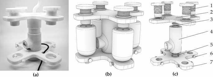
As illustrated in Fig. 4, the plug-and-push mechanism’s components and assembly are detailed. This mechanism primarily serves the bottle stopper piercer, ensuring it can smoothly penetrate the bottle stopper. Structurally, it is an upgraded version of a simple lead screw slide table. The combination of the bearing protection sleeve and bearings provides reliable rotational support for the smooth movement of the slider on the slide table. The slider is fixed to the piercer mounting plate via a connector, ensuring stability during the piercing process.
The rotational motion of the screw is driven by a motor, which is securely mounted on the device using a motor fixing plate, enabling linear movement of the slider. The slide table offers a precise motion track for the slider, ensuring linearity and high precision in the plug-and-push action. The motor accurately drives the screw, facilitating precise insertion and withdrawal of the piercer. The direct up-and-down transmission of the screw enhances the automation level of the device, improving the stability of the piercer’s longitudinal movement, thus ensuring reliability and high efficiency in practical applications.

Schematic of the plug-and-push mechanism: (a) actual photograph of the plug-and-push mechanism (b) model diagram of the mechanism (c) exploded view of the mechanism: (1. bearing protection sleeve, 2. bearing, 3. slider, 4. connector, 5. piercer mounting plate, 6. screw, 7. bearing, 8. slide table, 9. motor fixing plate, 10. motor)
When designing the plug-and-push mechanism for the smart infusion automatic medication replacement device, calculating the force required for the piercer to penetrate the bottle stopper and selecting an appropriate motor are crucial for ensuring efficient and reliable operation. As illustrated in Fig. 5, the following three aspects should be considered for selecting the compatible model:
-
1.
Required piercing force.
Piercer Diameter: d = 5 mm.
Shear Strength of Stopper Material:σ = 2 MPa.
The shear strength of common medical-grade silicone typically ranges from 0.5 to 2 MPa. The cross-sectional area (A) of the piercer is calculated as follows:
Calculate piercing force (F):
-
2.
Required torque.
The required torque (T) can be calculated based on the piercing force and the radius (r) of the lead screw:
Screw radius: r = 2.5 mm, Transmission efficiency: η = 0.85,Calculate torque (T):
-
3.
Required power (W).
With the motor speed set at 100 revolutions per minute (\(\:\omega\:\)), the required power (P) can be calculated as follows:

Distribution diagram for power calculations of the plug-and-push mechanism (1. piercing force, 2. torque, 3. power).
Based on the calculations, the required torque is 1.15 × 10− 7 NM, and the necessary power is 1.20 W. Consequently, a size 28 stepper motor was selected, featuring an outer diameter of 28 mm and a two-phase structure, with a rated current of 1.0 A and a rated voltage of 3.0 V. The motor’s maximum speed of 100 rpm aligns perfectly with the design specifications. This motor is well-suited for use under the design parameter conditions of the smart infusion automatic medication replacement device, providing ample performance assurance.
Stabilization and calibration mechanism
As depicted in Fig. 6, the stabilization and calibration mechanism is designed to ensure the stability and precise positioning of the medicine bottles during the replacement process. This mechanism comprises several precision components, including a securing cylinder, upper securing platform, upper bearing, central housing, lower bearing, bottle neck securing screw, and lower securing platform.
The securing cylinder is responsible for stabilizing the top of the medicine bottles, providing initial support. The upper and lower securing platforms are positioned at the two ends of the medicine bottles, offering rotational support through the upper and lower bearings to ensure the medicine bottles remains stable during the replacement operation. The central housing connects the upper and lower securing platforms, forming a complete stabilization structure. The bottle neck securing screw further anchors the medicine bottles neck, preventing any movement of the plug-and-push mechanism during operation.
Schematic of the stabilization and calibration mechanism: (a) actual photograph of the mechanism (b) model diagram of the mechanism (c) exploded view of the mechanism. components: (1. securing cylinder, 2. upper securing platform, 3. upper bearing, 4. central housing, 5. lower bearing, 6. bottle neck securing screw, 7. lower securing platform).
As shown in Fig. 7, this system employs a four-point stabilization method to effectively enhance the stability and positioning accuracy of the medicine bottles. Fig (a) demonstrates the actual fixed state of the bottles, while Fig (b) presents a schematic diagram of the simultaneous loading of the medication bag and bottles. Fig (c) and (d) illustrate the structural schematics of the loading fixation, highlighting the critical fixation points that stabilize the medicine bottles. This design secures the bottles at the bottom, body, and neck, ensuring that the bottles do not displace or rotate during the entire operation process. The fixed structure at the bottom provides initial support, preventing vertical movement of the bottles. The middle section of the bottle body is further reinforced by the lower fixed platform to enhance stability and effectively resist external disturbances. The neck of the bottle employs a screw knob fixation method to ensure that the bottle opening remains aligned at the predetermined center position during use, preventing rotation or displacement due to improper handling.
For the installation of the medication bag, a fixed hook structure is designed within the fixation device, ensuring that the medication bag is securely fixed at the tail end, maintaining a vertical orientation at all times. This design effectively avoids the risk of sliding or falling off the medication bag due to external forces. The fixed hook is made of TPU material and 3D printed, providing a certain level of elasticity. This design employs a non-rigid fixation method aimed at accommodating deformation caused by internal pressure changes during infusion, ensuring the vertical structure of the bottles and bags is maintained. The fixation of the bottle opening is achieved through the screw knob method, providing a robust securing effect to ensure that the opening remains centered at the designated position. Figure 7 clearly demonstrates this design logic. These carefully designed fixation points exhibit the stability and accuracy of the mechanism, fully meeting the reliability requirements of the medication delivery process.

Schematic of medicine bottles stabilization: (a) actual photograph of the vial stabilization (b) installation model diagram for medicine bottles and medicine bags (c) cross-sectional view of medicine bag fixation and (d) cross-sectional diagram of the medicine bottles stabilization points (1. securing hook, 2. bottom fixation, 3. body fixation, 4. neck fixation).
The combination of the securing cylinder and platforms allows the medicine bottles to remain stable throughout the replacement process, minimizing positioning errors caused by vibrations. The use of upper and lower bearings provides rotational support, facilitating smooth medicine bottles rotation during replacement and reducing mechanical friction and wear. The design of the central housing enhances the overall rigidity of the structure, ensuring a tight fit among all components. The inclusion of the bottle neck securing screw further improves the stabilization, preventing any displacement during operation.
The four-point stabilization design enhances the stability of the vial. The multi-point securing system at the bottom, body, and neck ensures the medicine bottles remains stable in all directions, preventing any displacement or rotation during operations. This modular stabilization design simplifies maintenance and cleaning of the equipment, further improving its reliability and longevity.
Rotational medication replacement mechanism
Structural description
As illustrated in Fig. 8, the rotational medication replacement mechanism is designed to automate the replacement of medicine bottles. This mechanism consists of a lower securing platform, a connecting disc, a flange, and a servo motor. The lower securing platform provides foundational support for the vial, ensuring stability during operation. The connecting disc links the lower securing platform and the flange, forming a complete rotational structure. The flange serves as the interface for the servo motor, ensuring it remains securely attached during rotation. The servo motor acts as the power source, enabling precise angular control to facilitate the rotational replacement of the vial.

Schematic of the rotational medication replacement mechanism: (a) actual photograph of the mechanism and (b) model diagram of the mechanism (1. lower securing platform, 2. connecting disc, 3. flange, 4. servo motor).
Through precise control by the servo motor, medicine bottles can be quickly and accurately rotated and replaced, reducing the need for manual intervention and operation time. The combination of the lower securing platform and connecting disc provides structural support, ensuring that the entire mechanism remains stable during rotation driven by the servo motor, thereby minimizing the risk of faults due to vibration or external forces.
Performance analysis
In this design, the rotary drug replacement mechanism is equipped with an HS-5485HB servo motor, which provides efficient and reliable support to the system through its superior performance. The servo motor operates at working voltages of 4.8 V and 6.0 V, with response speeds of 0.22 s/60° at 4.8 V and 0.18 s/60° at 6.0 V, demonstrating exceptional rapid operation capabilities. Moreover, in terms of torque, the motor generates 4.8 kg·cm at 4.8 V and can reach 6.0 kg cm at 6.0 V, providing stable power output for the rotation mechanism.
Considering the working conditions of the servo motor in the rotary drug replacement mechanism, an analysis was conducted on the motor’s driving capacity under full load. The rotation mechanism contains four medicine bottles, with the servo motor’s drive point located at the center of the entire system, as shown in Fig. 9. According to calculations based on bottle capacity and distribution, the mass of the bottles and their distance from the motor’s center are critical factors in assessing the motor’s reliable operation.

Rotation diagram.
Assuming each medicine bottle’s full capacity is 260 ml, the mass of each bottle would be approximately 260 g (with water density of 1 g/ml). Since the four bottles are positioned diagonally in the rotation mechanism, the distance from each bottle to the motor’s center is 70.55 mm. As the bottles are arranged in a square configuration, this is calculated as the diagonal distance from the center to each bottle. By utilizing this distance, the total load from the bottles can be converted into torque.
The formula for calculating the total torque required by the motor is:
Where n represents the number of bottles, and F represents the gravitational force of each bottle. The total load of the four bottles is:
The total required torque is:
According to the servo motor parameters, the HS-5485HB can provide a maximum torque of 6.0 kg·cm at 6 V. Clearly, the required torque of 0.734 kg·cm is far below the motor’s maximum output capability. This indicates that even when four medicine bottles are fully loaded, the motor can completely satisfy the driving requirements of the medicine replacement mechanism.
Liquid level monitoring mechanism
The liquid level monitoring mechanism is designed to monitor the liquid level of the medication in real-time, ensuring accuracy and safety during the infusion process. As shown in the cross-sectional schematic in Fig. 10, the mechanism includes the monitored liquid level, the liquid level sensor, and the wiring hole. The monitored liquid level represents the actual liquid level of the medication, which is continuously observed by the liquid level sensor installed within the monitoring chamber. This sensor precisely detects changes in the liquid level.
The design of the wiring hole allows the sensor’s connections to integrate seamlessly into the microcontroller housed in the lower casing, facilitating real-time data transmission and processing. This design allows for continuous monitoring of changes in the medication’s liquid level, ensuring the accuracy of the infusion process. The design of the monitoring chamber creates an enclosed environment, protecting the liquid level sensor from external interference.
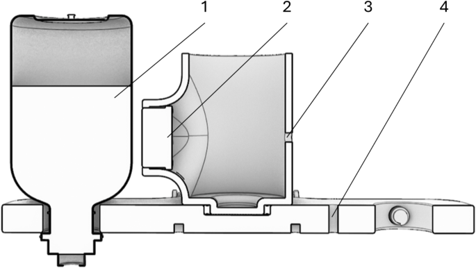
Cross-section diagram of the liquid level monitoring mechanism: (1. monitored liquid level, 2. liquid level sensor, 3–4. wiring hole).
The system employs a capacitive liquid level sensor as its core detection component. This sensor utilizes a non-contact detection principle, achieving a detection accuracy of ± 1.5 mm with a response time of 500ms, enabling high-precision real-time liquid level monitoring. The sensor features an IP67 protection grade, ensuring stable operation in medical environments. Its capability to detect through a 20 mm thick non-metallic container wall fully meets the monitoring requirements of standard infusion bottles. The NPN output interface facilitates easy integration with the control system, while its low power consumption of 5 mA guarantees long-term system stability. Detailed parameters are presented in Table 1.
The capacitive liquid level sensor has certain technical limitations, including specific requirements for the electrical conductivity of the measured liquid, potential electromagnetic interference, and specific container material constraints. However, considering that the majority of liquids used in clinical infusion therapy possess sufficient electrical conductivity, and infusion containers are typically made of non-metallic materials, these limitations do not significantly impede the sensor’s application in routine infusion monitoring. Compared to other types of liquid level sensors, the sensor used in this device not only meets basic functional requirements but also offers cost advantages and excellent adaptability, making it the optimal choice for smart infusion devices at the current stage.
From an application perspective, this sensor demonstrates significant practical value in routine infusion therapy. Firstly, the non-contact detection method completely eliminates direct contact between the sensor and the medication, adhering to the contamination-free requirements of medical equipment. The sensor’s detection accuracy and response speed satisfy the basic needs of clinical infusion monitoring. Its simple installation and maintenance facilitate easier adaptation in new equipment design and production. From a cost-effectiveness standpoint, the sensor provides an ideal price-performance ratio, which is particularly beneficial for the practical implementation of medical devices.
Relationships between core institutions
The structural design of the smart infusion device adopts a modular design concept, comprising four core mechanisms: liquid level monitoring mechanism, rotation and drug replacement mechanism, insertion and extraction mechanism, and stability calibration mechanism, as shown in Fig. 11.
The four core functional modules of the device have been spatially optimized: the liquid level monitoring mechanism utilizes high-precision sensors to real-time monitor the infusion status; the rotation and drug replacement mechanism employs a multi-position rotary platform to automatically replace medicine bottles; the insertion and extraction mechanism is responsible for precisely controlling the trajectory of the puncture needle; the stability calibration mechanism ensures the positioning of medicine bottles during the replacement process.

Core organizational structure chart.
The Component Box, serving as the control core of the device, achieves collaborative motion of the four core functional mechanisms through mechatronic design. The system’s workflow reflects the close cooperation between modules, with corresponding coordination among the four core mechanisms. Specifically, the liquid level monitoring mechanism and insertion and extraction mechanism are located on the left side of Fig. 11, with the insertion and extraction mechanism performing actions only after the liquid level sensor activates and detects the liquid; the rotation and drug replacement mechanism and stability calibration mechanism are positioned on the right side of the Fig, providing necessary stability support during rotation.When the liquid level is detected as insufficient, the liquid level detection mechanism and rotation and drug replacement mechanism interact to rotate and replace the medicine bottle on the work platform. The relationship between the stability calibration mechanism and insertion and extraction mechanism is focused on maintaining the bottle’s stability, ensuring that the puncture needle of the insertion and extraction mechanism can accurately penetrate the medicine bottle.
The relationships between the core mechanisms and their collaborative control method guarantee the reliability of coordination during the drug replacement process, thereby demonstrating the innovative value of this design in the medical device domain.
Chapter summary
This chapter provides a detailed analysis of the structural design and operational workflow of the smart infusion automatic medication replacement device. The device comprises key components such as the liquid level monitoring mechanism, rotational medication replacement mechanism, and plug-and-push mechanism. These components work in unison to achieve automated delivery and replacement of medication.
The liquid level monitoring mechanism continuously monitors the medication level, ensuring accuracy and safety during the infusion process. The rotational medication replacement mechanism, driven by a servo motor, facilitates rapid vial replacement. The plug-and-push mechanism ensures precise connection between the piercing tool and the vial. The operational workflow covers all stages from preparation and initiation to conclusion, highlighting the device’s effectiveness in reducing manual intervention and enhancing the continuity and safety of infusions. The optimization of these designs and processes provides strong support for increasing the automation of medical procedures.
Code and control
Device operation process
The operation process of the smart infusion automatic medication replacement device consists of five stages: preparation, initiation, infusion, replacement, and conclusion.
First, during the preparation stage, securely fix the vial or medication bag to the device, ensuring its stability, and attach the piercing tool to the mounting plate of the plug-and-push mechanism. Next, initiate the device by connecting to the power source, activating the control system, and conducting a system self-check. Once the liquid level monitoring mechanism is confirmed to be functioning correctly, the plug-and-push mechanism inserts the piercing tool into the bottle neck, and a doctor is notified for intravenous insertion.
During the infusion process, the liquid level monitoring mechanism continuously tracks the medication level. If the level drops below a preset value, the sensor transmits a signal to the microcontroller, triggering an alert to prompt vial replacement. The plug-and-push mechanism returns the fixing plate to its original position, and the rotational medication replacement mechanism automatically activates. The servo motor rotates the lower support plate by 90° to complete the vial replacement, and the plug-and-push mechanism moves the platform upwards to ensure the piercing tool accurately enters the new vial.
After replacement, the system confirms the new vial is properly installed, and the liquid level monitoring mechanism resumes its monitoring, allowing the device to continue with the infusion process. At the end of the operation, power off the device and call the doctor to remove the needle. This process enables efficient and safe delivery and replacement of medication, enhancing the automation of medical procedures. As shown in Fig. 12, the workflow diagram illustrates the operation of the smart infusion automatic medication replacement device.

Workflow diagram of the smart infusion automatic medication replacement device.
Liquid level monitoring
In designing our smart infusion pump system, we have selected capacitive sensors as the core technology for liquid level monitoring. This choice is based on their ability to meet the specific needs of the device and their suitability for application in medical environments. Capacitive sensors are capable of detecting various types of liquids, including opaque and viscous ones, by sensing changes in capacitance to determine the liquid level, unaffected by the color and transparency of the liquid. Additionally, their non-contact design minimizes direct contact with the liquid, reducing contamination risks, making them highly suitable for medical equipment use. High precision and reliability are other prominent advantages, meeting the stringent requirements of medical infusion and maintaining consistent performance over long-term use.
In complex medical environments, capacitive sensors excel, particularly under conditions of humidity, dust, or pressure variations, thanks to their excellent anti-interference capabilities, ensuring stability in electronically noisy environments. Our designed sensors are easily integrated with the smart infusion pump’s control system, allowing for flexible configuration through simple circuit adjustments. They can quickly respond to changes in liquid level, automatically adjusting infusion rates and dosages. This integration capability significantly reduces manual intervention and enhances the system’s automation level. Considering these advantages, capacitive sensors provide a reliable solution that balances performance and cost for our smart infusion pump system, making them the ideal choice for achieving continuous, precise, and safe infusion operations. The specific code for data processing and signal transmission of the liquid level monitoring system is shown below:


Rotating dressing changing mechanism
The core of the rotating and converting medication mechanism lies in its ability to rotate and convert efficiently. Through precise mechanical design, this mechanism can quickly switch between different medications, ensuring the rapid delivery of the correct dosage when needed. The rotating component is typically driven by a motor, allowing for precise control of rotation angle and speed to achieve accurate positioning and switching of medication containers. The control code for the rotating dressing change mechanism is as follows:


System status monitoring and feedback
The system status monitoring and feedback mechanism is a critical component in ensuring the reliable operation of the rotating and converting medication mechanism. By utilizing various sensors, such as position, speed, and temperature sensors, the system continuously gathers data on the equipment’s operational status and performance. This data is not only used to assess the health of the equipment but also to identify potential fault risks, thereby preventing issues before they occur.
The monitoring system feeds the collected data back to the control unit for real-time adjustments and optimization of operations. Additionally, it provides feedback to operators, including current status, warning messages, and operational suggestions, ensuring they are informed about the equipment’s condition and can make timely decisions.
Fault detection and diagnosis are vital components of the monitoring and feedback mechanism, enabling the automatic identification of faults or anomalies within the system and providing diagnostic information to facilitate quick problem resolution. Through log recording and analysis, the system can identify potential issues and optimization opportunities, thereby enhancing overall reliability and efficiency. This code will implement sensor data acquisition, status monitoring, data feedback, and fault detection, as detailed below:


Discussion
Performance testing experiment
To effectively utilize this device in real infusion environments, it is necessary to verify the performance of the smart infusion automatic medication replacement device under different loading conditions, particularly focusing on its rotational speed and medication loading efficiency. This experiment aims to comprehensively assess the performance and efficiency of the smart infusion automatic medication replacement device. The experimental plan covers several key stages, including preparation, design, process, objectives, and data analysis. During the preparation phase, researchers will gather the necessary experimental equipment, including the smart infusion automatic medication replacement device and various types and capacities of infusion bottles. They will also prepare timers and data recording sheets to ensure consistency in experimental conditions and reliability of data. The experimental design is divided into two parts: equal-ratio groups and unequal-ratio groups of bottle capacities, to thoroughly test the device’s adaptability.
The experimental process requires two people to collaborate: one to operate the device and the other to handle timing and recording. They will continuously test the medication replacement time for 2, 3, and 4 bottles, recording the total time and comparing single and overall replacement times, while also calculating averages and errors. The main objectives of the experiment include comparing the consistency of different capacity bottles during machine operation, evaluating the time saved for healthcare personnel by the device, eliminating the influence of regular bottle input conditions, comparing the operational time differences of bottles with different capacities, and testing the overall time differences of various combinations.
In the data analysis phase, each round’s single and overall replacement durations will be thoroughly analyzed, comparing the replacement efficiency of different capacity combinations, and assessing the consistency and stability of the device when handling bottles of varying capacities. Through this comprehensive experimental plan, researchers will be able to systematically evaluate the performance of the smart infusion automatic medication replacement device, including its efficiency, stability, and adaptability, providing crucial data support and theoretical basis for further optimization and practical application of the device. The experiment will analyze the impact of bottle capacity ratios on device performance through size effect analysis and discuss the optimal combination strategy for loading medications to improve the efficiency and safety of the infusion process, providing data support for clinical applications. The specific experimental plan is shown in Table 2.
As shown in Fig. 13, the setup and medical supplies prepared for the experiment demonstrate the preparatory work undertaken. Table 3 details the specifications of the medication bottles used. Figure 13 illustrates the critical equipment and tools necessary for the experiment. Centrally positioned is the smart infusion automatic medication replacement device. A tablet computer was employed in the experiment for precise timing. In the foreground of the Fig, multiple transparent plastic bottles of various sizes are displayed, each labeled to represent different experimental groups or types of medication. On the right, a glass beaker contains a simulated medication solution used for preparation during the experimental process. Table 3 lists in detail the parameters of the four different models of medication bottles used in the experiment. These bottles have capacities ranging from 50 ml to 200 ml, with corresponding brimful capacities from 68 ml to 260 ml. The bottle diameters increase as capacity increases, ranging from 46 mm to 61 mm. This diverse selection of bottle specifications reflects the comprehensiveness of the experimental design, aiming to test the device’s adaptability and handling efficiency across bottles of different sizes and capacities.

Tools for experiment preparation.
Figure 14 provides a detailed record of the specific operational details and key points in the experimental procedure, showcasing seven critical operational steps of the smart infusion automatic medication replacement device during the experiment. It explains the steps corresponding to the total timing. First, the medication bottle is securely mounted on the device (a), ensuring stability throughout the process. Next, the device rotates to precisely align the bottle with the liquid level monitor (b), preparing for subsequent level detection. Then, the puncture device is accurately inserted into the bottle neck (c), executed by the plug-pull mechanism to ensure a firm connection between the puncture device and the bottle neck. Subsequently, the liquid level monitor checks the liquid level position (d). If the level is not detected, the puncture device automatically returns to its initial position (e), preparing for the next bottle replacement. Following this, the servo motor drives the platform to rotate (f), which is the core operation of the rotary medication replacement mechanism, achieving rapid bottle replacement through precise control of the rotation angle. Once the bottle rotation replacement is completed (g), the plug-pull mechanism once again inserts the puncture device into the new bottle neck (e). This operation marks the end of a complete medication replacement cycle, with the new bottle in place, ready to start the next infusion round. The time recorded in the experiment is calculated from the intermediate process between steps (c) and (e).

Schematic diagram of the specific experimental procedure: (a) install the medicine bottle on the device (b) rotate to the front of the liquid level monitor (c) insert the puncture device into the mouth of the medicine bottle (d) the liquid level monitor checks the water level (e) the puncture device returns downward (f) the servo motor drives the platform to rotate (g) the medicine bottle completes the rotation and (e) insert the trocar into the new bottle opening.
During the implementation of the experiment, the performance of the smart infusion automatic medication replacement device will be systematically tested under different combinations of medication bottles. The necessary bottle combinations for the experiment are prepared, divided into equal-ratio groups and unequal-ratio groups. The equal-ratio group will test scenarios with bottles of the same capacity, while the unequal-ratio group will test combinations of bottles with different capacities. Load the corresponding bottles into the smart device, ensuring the stability and correct connection of the bottles. After starting the device, use an accurate timer to measure and record the time required for each medication replacement, ensuring data accuracy. To ensure data reliability and reproducibility, each bottle combination will be tested at least three times. Between each test, check the condition of the device and bottles to ensure no external factors affect the experimental results.
It is important to note that the timer may be subject to human error, typically between 1 and 2 s. This error mainly arises from human reaction time, operational proficiency, the precision of the timing equipment, and environmental factors. To minimize the impact of this error on the experimental results of the device, the accuracy of the data should be improved by measuring the replacement speed multiple times and taking the average value.
Test results
Equal proportion group test results
As shown in Table 4, according to the test data from the equal-ratio group, the smart infusion medication replacement device demonstrated good stability and consistency when handling medication bottles of varying capacities. From 50 ml to 200 ml bottles, the processing time for a single bottle increased slightly but remained minimal, with an average processing time ranging from 6.82 s to 7.17 s. The error margin (± 1 s) reflects potential minor fluctuations during actual operations, including mechanical error, human factors, and environmental influences. The total time for two equal-ratio bottles represents one complete operation cycle, i.e., finishing one medication replacement process; the total time for three equal-ratio bottles represents two operation cycles, as the third bottle needs to be replaced after the second bottle is finished; similarly, the total time for four equal-ratio bottles represents three operation cycles. This design simulates the scenario of continuous infusion in actual clinical practice, where each additional bottle requires an extra replacement operation cycle.
It should be noted that the total test time is based on continuous operation, completed in one go, and the medication filling process was therefore omitted. Consequently, some discrepancies may exist in practical applications. Nevertheless, the test results indicate that as the number of bottles increases, the total processing time exhibits an approximately linear growth, rising from about 7 s for a single bottle to approximately 28 s for four bottles. This linear growth trend demonstrates the device’s stable consistency and reliability during the continuous handling of multiple bottles. Even when processing larger 200 ml bottles, the device’s performance did not significantly decline, with the average processing time only about 0.35 s longer than that for 50 ml bottles. This suggests that the smart infusion medication replacement device has good adaptability and can efficiently handle bottles of different specifications, providing flexibility and efficiency for clinical applications.
Unequal proportion group test results
As shown in Table 5, the smart infusion medication replacement device exhibits excellent performance and adaptability when handling medication bottles of varying capacity combinations. In the two-bottle group, the average medication replacement time for the 100 ml + 50 ml combination is 7.30 s, while it increases to 7.66 s for the larger 150 ml + 200 ml combination, an increment of only 0.36 s. This indicates that the device maintains high efficiency even when dealing with larger capacity bottles. The 100 ml + 150 ml combination time (7.61 s) is slightly higher than the 50 ml + 200 ml combination (7.33 s), suggesting that bottle capacity might have some effect on medication replacement time. The data from the three-bottle group further highlights the device’s adaptability. The average replacement time for the 50 ml + 100 ml + 150 ml combination is 7.15 s, whereas it increases to 8.12 s for the larger 100 ml + 150 ml + 200 ml combination, an increment of 0.97 s. Although this increment is slightly larger than the two-bottle group, it still demonstrates excellent performance, considering the significant increase in total capacity. The 100 ml + 100 ml + 150 ml combination time (7.63 s) lies between the other combinations, further confirming the device’s adaptability to different capacity combinations. The data from the four-bottle group further confirms the device’s stability in complex situations. The average replacement time for the 50 ml + 100 ml + 150 ml + 200 ml combination is 7.41 s, whereas it increases to 8.09 s for the 100 ml + 150 ml + 200 ml + 200 ml combination, an increment of 0.68 s. When handling four bottles of different capacities, the device maintains relatively stable performance.
In combinations with the same number of bottles, those with larger total capacities generally require longer processing times, but the increments are not significant. In the four-bottle group, the combinations 50 ml + 150 ml + 150 ml + 200 ml and 100 ml + 100 ml + 150 ml + 200 ml have the same total capacity (550 ml), with average replacement times of 7.73 s and 7.85 s, respectively, a difference of only 0.12 s. This demonstrates the device’s strong adaptability to different capacities, allowing it to perform efficiently across various combinations.
In the four-bottle group with the 100 ml + 150 ml + 200 ml + 200 ml combination, the time for the first to third operations is 7.61 s, 8.22 s, and 8.45 s, respectively, showing a slight upward trend. As the number of operations increases, the time per replacement slightly rises. This might reflect cumulative effects during continuous operations, but the increment remains within a controllable range, not significantly affecting overall efficiency.
When handling multiple capacity combinations ranging from two to four bottles, the device consistently maintains an efficient and stable drug replacement time, averaging between 7.30 and 8.45 s. The increase in total volume leads to a minimal growth in replacement time. The device demonstrates the ability to handle various combinations of bottle numbers and volumes, maintaining nearly constant performance levels during continuous operations.
Equipment comprehensive assessment
-
1.
In terms of time efficiency.
Although traditional manual drug replacement methods are simple and direct, they have several efficiency bottlenecks, particularly in terms of medical staff movement time. Based on clinical observations and practical experience, we can analyze the traditional drug replacement process. Medical stations are typically located near infusion patients, with a maximum distance of approximately 25 m, considering sound propagation and emergency response time. The removal and replacement of intravenous needles are relatively quick, estimated to take 3–5 s. However, medical staff movement time becomes the primary time-consuming factor.Assuming medical staff walk at a speed of approximately 1.4 m per second, a round trip of 25 m would take about 36 s. Considering movement and actual operation time, each drug replacement process might require 39–41 s, excluding potential preparation time and patient interaction time, as specifically shown in Table 6.
In contrast, the smart infusion drug replacement device shows significant advantages. When handling the most complex combination of four bottles, the device completes a single drug replacement in about 7.5 s. This means that compared to traditional methods, the process of a single smart drug replacement can save approximately 31.5 to 33.5 s, which is a remarkable improvement, especially in busy medical environments.
Using the smart infusion drug replacement device, approximately 97.5 s can be saved after completing three replacements for each patient, marking a significant increase in time efficiency. If a doctor uses this device to assist around 30 patients each day, about 2,925 s can be saved, which is equivalent to approximately 48.75 min, thus reducing the repetitive workload of medical staff, as specifically shown in Table 7.
The formula for calculating the percentage increase in efficiency can be expressed as:
Among them, Ttr represents the total time for traditional methods, \(\:{T}_{i\:}\)represents the total time for innovative technology methods, and EIP stands for efficiency improvement percentage.
The conversion into efficiency improvement percentages reveals that the minimum efficiency improvement is calculated as (1 − 7.5/39) × 100% = 80.8%, while the maximum efficiency improvement is (1 − 7.5/41) × 100% = 81.7%. The device achieves an efficiency improvement range of 80.8–81.7%, significantly reducing the drug replacement time from 39 to 41 s to 7.5 s. This technological innovation has led to improvements in medical operation models, assisting healthcare professionals in reducing repetitive labor time, allowing them to devote more energy to complex clinical decisions and personalized patient care.
-
2.
In terms of error rate.
Error rate control is a key indicator for measuring device precision and reliability. In this study, the following calculation formula is used to quantitatively evaluate the error rate of drug replacement equipment.
Based on the average drug replacement time data from Table 5, basic error rate statistical data can be derived, as shown in Table 8.
Through data analysis, the average absolute error of the smart medication replacement device is 0.14 s. In different experimental groups, there is a minimal deviation between the actual operation time of the device and the ideal time, with no evidence of systematic error. The maximum absolute error is only ± 0.20 s, indicating consistency and stability in the device’s operations, with virtually no significant performance fluctuations. The error rate ranges between − 2.67% and 2.67%, demonstrating that the device can operate stably across various combinations of medication bottles and adapt to different operational environments. The standard deviation is 0.14, indicating that the distribution of the device’s operation time is relatively concentrated with minimal fluctuation, which is an important reference standard for ensuring the efficiency and quality of the medication replacement process.
The data from this experiment effectively validates the excellence of the smart medication replacement device in terms of operational efficiency and error control, highlighting its potential value in clinical applications. However, the current testing is still in the prototype phase, with a limited sample size, and is intended only for feasibility analysis of the device. Therefore, these results only validate the technical feasibility of the device. In the future, more user research and experiential testing are needed to further improve the device’s performance and ensure its effectiveness and applicability in real medical environments.
Outlook
The smart infusion automatic medication replacement device introduces a novel infusion method in infusion therapy. By utilizing a high-precision liquid level monitoring module, the device tracks the liquid level in real-time, reducing the need for continuous monitoring by patients and medical staff. The automated medication replacement function, through a rotary medication replacement mechanism and a plug-push system, allows for quick and accurate bottle replacement, primarily reducing repetitive labor for medical staff and enabling them to focus on other tasks.
The smart infusion automatic medication replacement device designed in this study also presents some practical usage challenges. The integration of various high-precision and automated technologies increases the complexity of the device, raising the usage threshold for some patients during infusion. Therefore, the widespread adoption of such devices requires extensive time for user research and exploration of usage habits.
The high degree of automation may lead medical personnel to become more reliant on automated medication replacement methods. Although no operational failures occurred during the experiment, potential malfunctions could test the temporary operational skills of doctors, possibly affecting the continuity of the infusion process. Therefore, medical staff need specialized training to operate the equipment proficiently, which may increase training costs and time for hospitals.
The design process of the device initially focused primarily on structural design for functional realization, ensuring that the components used met the necessary functional requirements and verifying the feasibility of the device design. To enhance the overall usability and effectiveness of the device, future improvements for the second-generation device will include several key aspects. First, the operation workflow will be simplified; despite the complex technical integration, medical staff will still be able to quickly get started using the device. The operation process will be streamlined through intuitive button controls, allowing medical personnel to become familiar with the system in a short time. Second, smart prompts and fault diagnosis functions will be introduced, which will timely alert medical personnel to any abnormalities in the device and provide simple troubleshooting steps. This feature will help medical staff quickly respond to potential failures, thereby reducing reliance on temporary operational skills. Finally, a user feedback mechanism will be implemented in the device design, regularly collecting medical personnel’s usage experiences and suggestions. This user-driven approach will continuously optimize the device’s functions, thereby lowering the usage threshold and enhancing the practical effectiveness of the device.
Through these improvements and optimizations, the next generation of smart infusion automatic medication replacement devices will play a greater role in enhancing infusion therapy speed, simplifying both medical and patient operations, and improving the patient treatment experience. Future research should continue to explore the multifunctionality and smart management potential of these systems to further advance the medical industry.
Conclusion
The smart infusion automatic medication replacement device designed in this study integrates a variety of innovative mechanisms to enhance the efficiency, precision, and safety of medication delivery. By incorporating advanced liquid level monitoring, automated rotational replacement, and a precision plug-and-push system, the device significantly reduces manual intervention and operational errors. Its modular enclosure design and multi-point stabilization further ensure adaptability and reliability, making it suitable for diverse medical environments. Specifically, the innovative features of this device include:
-
1.
Advanced Liquid Level Monitoring: This device features a high-precision liquid level sensor for real-time tracking, reducing infusion errors by ensuring accurate medication administration and enhancing patient safety.
-
2.
Automated Rotational Medication Replacement: Using a servo motor, the rotational mechanism enables rapid and precise vial changes, decreasing manual intervention, and improving delivery efficiency in high-demand settings.
-
3.
Precision Plug-and-Push Mechanism: The motor-driven plug-and-push system provides stable connections for piercing medicine bottles, enhancing precision and consistency in medication delivery.
-
4.
Modular Enclosure Design: Constructed with 3D printing technology, the modular enclosure allows quick prototyping and customization, simplifying maintenance and upgrading while increasing device adaptability.
-
5.
Multi-Point Stabilization and Calibration: This innovation secures medicine bottles at multiple points, minimizing errors from vibrations and ensuring stable, reliable operation throughout the replacement process.
In conclusion, the smart infusion automatic medication replacement device enhances the automation of medication delivery and replacement, significantly reducing the workload of healthcare providers and improving the safety and consistency of patient treatment. These designs and optimizations provide a solid foundation for advancing the automation of medical procedures, promising to increase the efficiency and reliability of healthcare delivery systems. Future research should focus on further refining these technologies to meet the diverse needs of modern medical environments and explore the potential of smart automated medication management in the future of healthcare.
Data availability
The authors attest that all data for this study are included in the paper.
References
Heald, A., Bramham-Jones, S. & Davies, M. Comparing cost of intravenous infusion and subcutaneous biologics in COVID‐19 pandemic care pathways for rheumatoid arthritis and inflammatory bowel disease: a brief UK stakeholder survey. Int. J. Clin. Pract. 75, 789 (2021).
Gorski, L. A. A look at 2021 infusion therapy standards of practice. Home Healthc. Now 39, 62–71 (2021).
Rzepczyk, S. et al. Causes of death during the intravenous infusion of dimethylsulphoxide and hydrogen peroxide in the course of alternative medicine therapy. Toxics 11, 652 (2023).
Kichula, E. A. et al. Expert recommendations and clinical considerations in the use of onasemnogene abeparvovec gene therapy for spinal muscular atrophy. Muscle Nerve 64, 413–427 (2021).
Oros, D. et al. Smart intravenous infusion dosing system. Appl. Sci. 11, 513 (2021).
Manrique-Rodríguez, S. et al. Standardization and chemical characterization of intravenous therapy in adult patients: a step further in medication safety. Drugs R D 21, 39–64 (2021).
Schaefer, B. et al. Hypophosphatemia after intravenous iron therapy: comprehensive review of clinical findings and recommendations for management. Bone 154, 116202 (2022).
Epstein, R. S. Payer perspectives on intravenous versus subcutaneous administration of drugs. CEOR 13, 801–807 (2021).
McDonald, C. M. et al. Repeated intravenous cardiosphere-derived cell therapy in late-stage Duchenne muscular dystrophy (HOPE-2): a multicentre, randomised, double-blind, placebo-controlled, phase 2 trial. Lancet 399, 1049–1058 (2022).
Liu, S., Jiang, L. & Wang, X. Intelligent internet of things medical technology in implantable intravenous infusion port in children with malignant tumors. J. Healthcare Eng. 2021, 1–9 (2021).
Nickel, B. et al. Infusion therapy standards of practice. J. Infus. Nurs. 47, S1–S285 (2024).
Overton, P. M., Shalet, N., Somers, F. & Allen, J. A. Patient preferences for subcutaneous versus intravenous administration of treatment for chronic immune system disorders: a systematic review. PPA Volume 15, 811–834 (2021).
Honmou, O. et al. Intravenous infusion of auto serum-expanded autologous mesenchymal stem cells in spinal cord injury patients: 13 case series. Clin. Neurol. Neurosurg. 203, 106565 (2021).
Raikar, A. S., Kumar, P., Raikar, G., Vedant, S., Somnache, S. N. & (& Advances and challenges in IoT-based smart drug delivery systems: a comprehensive review. Appl. Syst. Innov. 6, 62 (2023).
Hagle, M. et al. Using a patient safety analysis to guide infusion therapy for patients with COVID-19. J. Infus. Nurs. 44, 259–267 (2021).
Reddy, D. R., Prakash, S., Dinakar, A., Kumar, S. & Kodali, P. Smart saline monitoring system for automatic control flow detection and alertness using IoT application. In Congress on Intelligent Systems (eds. Sharma, H. et al.) 745–757 (Springer, 2021).
Bai, X., Wang, Q. & Cao, S. Application of infusion control system based on internet of things technology in joint orthopedics nursing work. J. Healthcare Eng. 2021, 1–11 (2021).
Astuti, A. R., Rahmawati, T. & Phasinam, K. The performance analysis of the infrared photodiode sensor to infusion set on infusion device analyzer machine. J. Electron. Electromed. Eng. Med. Inf. 5, 25–32 (2023).
Sharma, R., Singh, D., Gaur, P. & Joshi, D. Intelligent automated drug administration and therapy: future of healthcare. Drug Deliv Transl Res. 11, 1878–1902 (2021).
Burrai, F., De Marinis, M. G. & Piredda, M. Virtual reality during chemotherapy infusion: an innovative intervention in holistic nursing practice. Holist. Nurs. Pract. 38, 220–226 (2024).
Mehdiratta, L. & J. S. Bajwa, S. Technology, engineering and innovations-Power buffers in the COVID driveline…. Indian J. Anaesth. 65, 351–355 (2021).
Lu, J., Wang, Y., Li, X., Zhang, J. & Chen, L. Design of an infusion set based on pulse control and gravitational potential energy speed regulation. In IEEE 5th Advanced Information Technology, Electronic and Automation Control Conference (IAEAC) 1531–1535 (IEEE, 2021).
Opait, E. E., Silion, D., Iftene, A., Luca, C. & Corciova, C. Mixed realities tools used in biomedical education and training. In International Conference on INnovations in Intelligent SysTems and Applications (INISTA) 1–6 (IEEE, 2024).
Syed, M. A. et al. An epidemic of pediatric HIV from reuse of infusion equipment in Pakistan. JAIDS J. Acquir. Immune Defic. Syndr. 89, 121–128 (2022).
Al Ameen, M., Liu, J. & Kwak, K. Security and privacy issues in wireless sensor networks for healthcare applications. J. Med. Syst. 36, 93–101 (2012).
Al-Kahtani, M. S., Khan, F. & Taekeun, W. Application of internet of things and sensors in healthcare. Sensors 22, 5738 (2022).
Angelov, G. V., Nikolakov, D. P., Ruskova, I. N., Gieva, E. E. & Spasova, M. L. Healthcare sensing and monitoring. In Enhanced Living Environments (eds. Ganchev, I. et al.) 226–262 (Springer International Publishing, 2019).
Ciuti, G., Ricotti, L., Menciassi, A. & Dario, P. MEMS sensor technologies for human centred applications in healthcare, physical activities, safety and environmental sensing: a review on research activities in Italy. Sensors 15, 6441–6468 (2015).
Dhanvijay, M. M. & Patil, S. C. Internet of things: a survey of enabling technologies in healthcare and its applications. Comput. Netw. 153, 113–131 (2019).
Formica, D. & Schena, E. Smart sensors for healthcare and medical applications. Sensors 21, 543 (2021).
Gardašević, G., Katzis, K., Bajić, D. & Berbakov, L. Emerging wireless sensor networks and internet of things technologies—foundations of smart healthcare. Sensors 20, 3619 (2020).
Hao, Y. & Foster, R. Wireless body sensor networks for health-monitoring applications. Physiol. Meas. 29, R27 (2008).
He, R., Teng, C., Kumar, S., Marques, C. & Min, R. Polymer optical fiber liquid level sensor: a review. IEEE Sens. J. 22, 1081–1091 (2021).
Hernandez, N. et al. Scoping review of healthcare literature on mobile, wearable, and textile sensing technology for continuous monitoring. J. Healthc. Inf. Res. 5, 270–299 (2021).
Javaid, M., Haleem, A., Rab, S., Singh, R. P. & Suman, R. Sensors for daily life: a review. Sens. Int. 2, 100121 (2021).
Kumar, S. & Singh, R. Recent optical sensing technologies for the detection of various biomolecules. Opt. Laser Technol. 134, 106620 (2021).
Lai, Y. et al. Elastic multifunctional liquid–metal fibers for harvesting mechanical and electromagnetic energy and as self-powered sensors. Adv. Energy Mater. 11, 2100411 (2021).
McGrath, M. J. & Scanaill, C. N. Sensor Technologies: Healthcare, Wellness, and Environmental Applications (Springer Nature, 2013).
Neves, P., Stachyra, M. & Rodrigues, J. Application of wireless sensor networks to healthcare promotion. J. Commun. Softw. Syst. 4, 181–190 (2008).
Nguyen, H. H., Mirza, F., Naeem, M. A. & Nguyen, M. A review on IoT healthcare monitoring applications and a vision for transforming sensor data into real-time clinical feedback. In IEEE 21st International conference on computer supported cooperative work in design (CSCWD) 257–262 (IEEE, 2017).
Shah, S. A., Abbas, H., Imran, M. A. & Abbasi, Q. H. Rf sensing for healthcare applications. In Backscattering RF Sens. Future Wirel. Communication 157–177 (2021).
Shah, S. A. & Fioranelli, F. RF sensing technologies for assisted daily living in healthcare: a comprehensive review. IEEE Aerosp. Electron. Syst. Mag. 34, 26–44 (2019).
Sharma, A., Singh, A., Gupta, V. & Arya, S. Advancements and future prospects of wearable sensing technology for healthcare applications. Sens. Diagn. 1, 387–404 (2022).
Wu, M. Wearable technology applications in healthcare: a literature review. On-Line J. Nurs. Inf. 23, 789 (2019).
Yan, H. et al. An emerging technology—wearable wireless sensor networks with applications in human health condition monitoring. J. Manage. Anal. 2, 121–137 (2015).
Yeo, J. C. & Lim, C. T. Emerging flexible and wearable physical sensing platforms for healthcare and biomedical applications. Microsyst. Nanoeng. 2, 1–19 (2016).
Zang, Y., Zhang, F., Di, C. & Zhu, D. Advances of flexible pressure sensors toward artificial intelligence and health care applications. Mater. Horiz. 2, 140–156 (2015).
Aslam, N. et al. Quantum sensors for biomedical applications. Nat. Rev. Phys. 5, 157–169 (2023).
Chen, S. et al. Piezocatalytic medicine: an emerging frontier using piezoelectric materials for biomedical applications. Adv. Mater. 35, 2208256 (2023).
Chircov, C. & Grumezescu, A. M. Microelectromechanical systems (MEMS) for biomedical applications. Micromachines 13, 164 (2022).
Mohankumar, P., Ajayan, J., Mohanraj, T. & Yasodharan, R. Recent developments in biosensors for healthcare and biomedical applications: a review. Measurement 167, 108293 (2021).
Yokota, T., Fukuda, K. & Someya, T. Recent progress of flexible image sensors for biomedical applications. Adv. Mater. 33, 2004416 (2021).
Gorski, L. A. et al. Infusion therapy standards of practice. J. Infus. Nurs. 44, S1–S224 (2021).
Kok, C. L. et al. A novel low-cost capacitance sensor solution for real-time bubble monitoring in medical infusion devices. Electronics 13, 1111 (2024).
Kok, C. L. et al. A novel and Low-Cost Cloud-Enabled IoT integration for sustainable remote intravenous therapy management. Electronics 13, 1801 (2024).
Aborujilah, A., Elsebaie, A. E. F. M. & Mokhtar, S. A. IoT MEMS: IoT-based paradigm for medical equipment management systems of ICUs in light of COVID-19 outbreak. Ieee Access. 9, 131120–131133 (2021).
Cornejo, J. et al. Anatomical engineering and 3d printing for surgery and medical devices: international review and future exponential innovations. BioMed. Res. Int. 2022, 6797745 (2022).
Haber, N. & Fargnoli, M. Sustainable product-service systems customization: a case study research in the medical equipment sector. Sustainability 13, 6624 (2021).
Hang, N. T. et al. Further analysis on internet of things (IOT) applications in emerging markets and Vietnam. In Ambient Communications and Computer Systems (eds. Hu, Y. C. et al.) 407–416 (Springer Nature, 2022).
Irfan, U. et al. 3D printing for development of medical equipment amidst coronavirus (COVID-19) pandemic—review and advancements. Res. Biomed. Eng. 38, 305–315 (2022).
Karthick, R., Ramkumar, R., Akram, M. & Kumar, M. V. Overcome the challenges in bio-medical instruments using IOT–A review. Mater. Today: Proc. 45, 1614–1619 (2021).
Pradhan, B., Bhattacharyya, S. & Pal, K. IoT-based applications in healthcare devices. J. Healthcare Eng. 2021, 1–18 (2021).
Ng, W. H. S. & Smith, S. D. Laser-assisted drug delivery: a systematic review of safety and adverse events. Pharmaceutics 14, 2738 (2022).
Funding
This research was funded by 2021 Hubei Provincial Philosophy and Social Science General Project (grant number: 21Y085), Graduate Innovative Fund of Wuhan Institute of Technology (grant number: CX2024211) and Key Project of the Humanities and Social Sciences Key Research Base “Ecological Environment Design Research Center” of Hubei Provincial General Colleges and Universities (grant number: 202301).
Author information
Authors and Affiliations
Contributions
B.M.:supervision, writing—review and editingY.W. and X.L.: investigation, methodology, and writing—original draft preparationM.C.:supervision, resources, writing—review and editingM.B., H.W., W.Z., and L.W.:investigationY.F.:writing—review and editingK.D.:investigation and methodology.
Corresponding author
Ethics declarations
Competing interests
The authors declare no competing interests.
Additional information
Publisher’s note
Springer Nature remains neutral with regard to jurisdictional claims in published maps and institutional affiliations.
Rights and permissions
Open Access This article is licensed under a Creative Commons Attribution-NonCommercial-NoDerivatives 4.0 International License, which permits any non-commercial use, sharing, distribution and reproduction in any medium or format, as long as you give appropriate credit to the original author(s) and the source, provide a link to the Creative Commons licence, and indicate if you modified the licensed material. You do not have permission under this licence to share adapted material derived from this article or parts of it. The images or other third party material in this article are included in the article’s Creative Commons licence, unless indicated otherwise in a credit line to the material. If material is not included in the article’s Creative Commons licence and your intended use is not permitted by statutory regulation or exceeds the permitted use, you will need to obtain permission directly from the copyright holder. To view a copy of this licence, visit http://creativecommons.org/licenses/by-nc-nd/4.0/.
About this article

Cite this article
Mu, B., Wang, Y., Liu, X. et al. Design research on a smart infusion device to reduce medical workload and enhance patient safety. Sci Rep 15, 9265 (2025). https://doi.org/10.1038/s41598-025-93911-8
Received:
Accepted:
Published:
Version of record:
DOI: https://doi.org/10.1038/s41598-025-93911-8
