
Abstract
In nature, raptors exhibit remarkable hunting abilities through their adept use of rapid aerial maneuvers. The key to achieving such exceptional maneuverability lies in the dynamic adjustment of the distance between the center of gravity (COG) and aerodynamic center (AC) over a wide range. Here, we report a biomimetic flapping-wing robot with agile flight capabilities. By coordinating adjustments in wing-tail distance and tail attitude, we can effectively manipulate the relative positioning of the robot’s COG and AC, as well as modulate wing and tail moments relative to COG, thereby influencing climbing and descending characteristics. This enhanced agility allows us to define and achieve 13 Dynamic Flying Primitives (DFPs). Furthermore, by combining different DFPs, nine highly challenging longitudinal agile maneuvers were achieved. Finally, outdoor flight tests have validated that our biologically inspired flapping-wing robot equipped with a self-adjustment strategy for wing-tail coordination can achieve agile maneuverability.
Introduction
The biomimetic flapping-wing robot, drawing inspiration from avian species in nature, demonstrates the potential for enhanced flight efficiency by optimizing airflow utilization, thereby presenting promising applications in disaster rescue operations, resource exploration endeavors, airport bird repellent systems, and other relevant domains1. However, existing flapping-wing robots are hindered by limitations such as suboptimal flying speeds and insufficient maneuverability, which impede their practical applicability. For instance, their limited maneuverability proves inadequate in effectively deterring avian species when deployed for bird repelling purposes at airports. Therefore, it is crucial to enhance the robot’s maneuverability in order to augment its efficacy in adversarial or aggressive tasks2. Furthermore, in scenarios characterized by limited spatial constraints and challenging airflow conditions, such as navigating through narrow canyons, dense forests, or complex urban environments, the attainment of high maneuverability becomes imperative to enhance the environmental adaptability of flapping-wing robots. The robots can effectively evade obstacles by adjusting their flight trajectory through rapid maneuvers while maintaining high velocities3. Consequently, the attainment of elevated levels of maneuverability during flight emerges as a pivotal aspect necessitating further breakthroughs within the realm of flapping-wing robotics in future research endeavors4,5,6.
Birds of prey, such as eagles, exhibit remarkable aerial agility in their natural habitat by effectively manipulating aerodynamic forces through wing morphology and flapping kinematics. Moreover, they possess the ability to manipulate their COG through alterations in wing shape and positioning, as well as adjustments in leg placement. The flight dynamics configuration of birds is determined by the interplay between aerodynamic force and COG, exerting a profound impact not only on stability but also on attitude control, speed regulation, and maneuvering characteristics that are indispensable for maintaining balance7,8,9.
Currently, conventional flapping-wing robots are limited in achieving intricate maneuvering flight comparable to fixed-wing aircraft and are restricted to basic flight maneuvers. The research on highly maneuverable flight has attracted considerable interest from researchers. In the field of avian-inspired fixed-wing robots, such as Lishawk10, PigeonBot11, and others12,13,14,15, remarkable maneuverability has been achieved through wing deformation; however, they still rely on supplementary propulsion systems like propellers for forward thrust instead of exclusively relying on flapping wings to emulate natural avian flight. In the field of biomimetic flapping-wing robots, Ramezani et al.16, Ollero et al.17,18,19,20, Chen et al.21, and others22,23,24 have developed bird-like and bat-like robots capable of achieving varying degrees of maneuverability through asymmetrical wing deformation. However, their effectiveness is constrained in intricate environments where achieving high maneuverability proves challenging.
The current flapping wing robot generally lacks the ability to modify its aerodynamic layout during cruise flight (the position of the AC and COG remains relatively fixed). The adjustment of flight direction and attitude can only be achieved by adjusting the flapping pattern of the wings and the motion of the tail25,26. However, this adjustment motion generates a small amplitude of aerodynamic moment, resulting in limited maneuverability that fails to meet the high maneuverability requirements for diverse flight conditions and tasks27,28. Birds have successfully overcome this issue. In the natural environment, avian species possess the ability to adapt their body posture and wing configuration in order to manipulate the COG29,30. As illustrated in Fig. 1a, c, d, birds can adjust their body’s COG by extending or tucking their wings and tail, as well as by adjusting the positioning of their leg muscles forward or backward, thereby affecting their pitch maneuverability.

a The high maneuverability flight of eagles in nature. b The prototype of biomimetic flapping wing robot—HIT-Hawk. c Birds are capable of modulating their body’s COG through wing morphing and adjustment of leg muscle positioning. The biomimetic flapping wing robot—HIT-Hawk, drawing inspiration from avian species, exhibits enhanced maneuverability in flight by employing a wing-tail distance adjustment mechanism to dynamically regulate the wing-tail distance, thereby effectively manipulating the COG of the robot. d Birds can reduce flight resistance and increase flight speed by tucking their tails during highly maneuverable dive and cruise flights. The HIT-Hawk employs a deformation mechanism to achieve tail extension and tucking, enabling tail expansion during high maneuverability flight for enhanced maneuverability. Conversely, the tail is tucked during diving and cruising flights to minimize aerodynamic drag, thereby improving flight efficiency and reducing power consumption. (The bird images in a, c, d are adapted from https://www.vcg.com/ with permission from the Beijing Vision Yimei Image Technology Co., Ltd. The detailed image ID number are: VCG211321579350, VCG41N2189275580, VCG41N2200094510, VCG41N2190121824,VCG211379896162, VCG41N1218804955 and VCG41157617824 respectively.)
Drawing inspiration from the exceptional maneuverability exhibited by avian species, a biomimetic flapping-wing robot with agile flight capability has been designed (as shown in Fig. 1b–d). The relative relationship between COG and AC can be effectively modified across a broad spectrum by precisely adjusting both wing-tail distance and tail posture. Consequently, the flight attitude can be dynamically adjusted based on the current flight state, thereby achieving an optimal distribution of aerodynamic torque to meet the demanding requirements of complex high maneuverability flights. By establishing an aerodynamic model and theoretically analyzing conditions for high maneuverability, complex maneuver analysis are decomposed into multiple Dynamic Flying Primitives (DFPs, Dynamic Flying Primitives refer to the basic primitives of flying motion for flapping-wing robots. Flying primitives can be combined into more complex trajectories to achieve advanced flying motion control of robots.)31: ascend and pull-up, ascend and inverted flight, dive and inverted flight, etc. Subsequently, a series of experiments were conducted to successfully accomplish 9 challenging maneuvers, including “upward somersaults, downward somersaults, figure of “8” somersaults, continuous upward somersaults, continuous downward somersaults, upward snake maneuver, downward snake maneuver, inverted maneuvers and large angle dive and climb steeply maneuvers”. The aforementioned maneuver flights have been successfully accomplished on the flapping-wing robot, exhibiting a level of maneuverability that rival the natural bird.
Results
A biomimetic flapping-wing robotic system with variable configuration
In order to conduct a more in-depth study on the maneuverability laws of bird flight, and based on the study of bird flight motion principles with appropriate simplification, a biomimetic flapping wing robot with variable configuration is designed as shown in Fig. 2a (Supplementary Movie 1). The prototype primarily comprises the fuselage shell, skeleton, flapping mechanism, wings, morphing tail, distance adjustment mechanism between wings and tail, electronic measurement and control components, as well as associated accessory components.
-
(a)
Transmission system and flapping mechanism: The schematic diagram of the transmission system and flapping mechanism is shown in Fig. 2b. The transmission system comprises a brushless DC (Direct Current, DC) motor and a two-stage gear reduction mechanism, while the flapping mechanism consists of a crank, a ball joint connecting rod, and a rocker. The rotational speed of the brushless DC motor in this mechanism is attenuated through a two-stage gear system, which drives the crank to execute circular motion, thereby propelling the rocker into oscillatory movement and ultimately achieving reciprocating flapping motion of the wings. Simultaneously, in order to minimize the influence of lateral motion on longitudinal maneuvering analysis and ensure the lateral rolling stability of the prototype throughout the maneuvering process, we established a flapping stroke angle range between −5° and 40° based on the size and structural characteristics of the prototype. The schematic diagram of the flapping stroke angle is illustrated in Fig. 2b, with an approximate wing dihedral angle of 17.5° in this configuration. Notably, the prototype experiments have demonstrated exceptional rolling stability and crosswind resistance during outdoor flight.
-
(b)
Morphing tail adjustment module: The tail adjustment module is mainly used for balancing flight and providing pitch, roll, and yaw moments for robot’s maneuvering. The structural diagram is presented in Fig. 2d (Supplementary Movie 3), comprising three servos, corresponding linkage mechanisms, and artificial feathers. Two of the pitch motion adjustment servos drive the entire tail to perform pitch motion around the Y-axis, while the yaw motion adjustment servo also drives the tail to perform a yaw motion around the Z-axis. The tail morphing adjustment servo propels the slider to execute reciprocating motion via a connecting rod, thereby actuating the rod connected to the artificial feather to move and achieve tail’s deformation.
-
(c)
Distance adjustment module between wings and tail: The COG position of conventional flapping-wing robots is basically fixed, and the flight direction and attitude can only be changed by adjusting the frequency of wing flapping and the direction of tail’s deflection. The amplitude of this adjustment is constrained, rendering it inadequate for fulfilling the demands of highly maneuverable flight tasks. Therefore, a variable distance adjustment mechanism is imperative to dynamically alter the COG of the robot during its flight process, thereby enhancing maneuverability. As depicted in Fig. 2c (Supplementary Movie 2), upon receiving control instructions, the DC deceleration motor drives the gear to initiate rotation. Consequently, the connected rack undergoes reciprocating motion under the influence of this gear, thereby adjusting the wing-tail distance to alter the COG position during robot flight.
-
(d)
Measurement and control system module onboard: The hardware part of this module comprises electronic components, main control board, and various sensor modules, as shown in Fig. 2e. Specifically, it includes batteries, brushless motors, electronic speed controller, remote control receivers, servos (servo 1 and 2 synchronously adjust the direction of yaw, asynchronous adjust the direction of pitch, servo 3 controls tail morphing), measurement systems onboard, flight control boards, GPS, hall sensors, magnetic encoders, etc.

a The structure composition of a variable configuration biomimetic flapping robot (Remote Control, RC). b Transmission system and flapping mechanism: After being decelerated by a reduction gear set, the brushless motor drives the rocker to swing with a flapping stroke angle of 45° under the action of the crank and connecting rod. c The distance adjustment module between wings and tail (Direct Current, DC). d The morphing tail adjustment mechanism. e Electronic components, measurement and control system onboard of the flapping-wing robot (ESC Electronic Speed Controller, MCU Microcontroller Unit, GPS Global Positioning System).
After integrating the various modules of the robot, the detailed performance parameters of the robot are obtained, as shown in Table 1. Under natural conditions, this bionic flapping-wing aircraft exhibits excellent wind resistance, capable of maintaining normal flight in level 5 wind conditions. This capability has been validated through outdoor flight testing (please refer to Supplementary Notes 3 of the Supplementary Information).
Implementation of high maneuver flight
In practical flight scenarios, the control of flapping-wing robots often relies on experiential and habitual factors, involving a comparison between command requirements and existing flight states. The linear function relationship between control variables and state parameters satisfies:
In the formula(1), y* represents the control variable, xcom represents the expected state parameter; x* represents the current state parameter; k, b is a constant that reflects the manipulation method. According to the motion equation of flapping-wing robots, x* is a function of throttle, the wing-tail distance, tail area, and elevator, denoted as:
As shown in Eqs. (3) and (4), A is set as the action space, which includes a series of standard operations that can describe the maneuvering flight control. The combination of these operations can comprehensively depict the entire process of maneuvering flight. δT, ∆l, ∆s, ∆e respectively represents the increment of throttle lever movement, the wing-tail distance, tail area, and tail pitch angle per unit time. Each operation can be numbered as 0,1,2, where 0 represents maintaining the original state and 1 represents increasing the amount of change; 2 indicates decreasing the amount of change. Action space A contains a total of 81 standard flight operations:
where aijkm (i = 0,1,2; j = 0,1,2; k = 0,1,2; m = 0,1,2) represents the combination of throttle, the wing-tail distance, tail area, and pitch angle of tail per unit time, representing flight operation instructions for each stage.
A large-scale biomimetic flapping-wing robot with variable configuration was designed to meet the requirements of high maneuverability for different complex environmental task scenarios. By implementing different maneuvering strategies, a variety of somersault maneuvers have been achieved such as upward somersaults, downward somersaults, figure of “8” somersaults, continuous upward somersaults, continuous downward somersaults, upward snake maneuver, downward snake maneuver, inverted maneuvers and large angle dive and climb steeply maneuver. The specific flight strategy for each maneuver along with the corresponding experimental results are elaborated below.
Typical somersault maneuvers
The somersault maneuver is a commonly employed high angle of attack longitudinal maneuver. Its primary objective is to ameliorate the unfavorable situation encountered during vertical maneuvers. It is one of the typical maneuvers of flapping-wing robots during flight, which refers to the flight process where the trajectory approximates an ellipse in the vertical plane and the heading direction changes by 360° or more. According to the different types of somersaults, they can be divided into upward somersaults, downward somersaults, figure of “8” somersaults, continuous upward somersaults, continuous downward somersaults, upward snake maneuver, and downward snake maneuver. Due to limitations in the length of the paper, this section only analyzes the typical figure of “8” somersault as a typical representative of somersault maneuvers. For other types of somersault maneuvers, please refer to the Supplementary Information (Supplementary Notes 1).
The figure of “8” somersault maneuver in the vertical plane involves executing a trajectory exclusively within the vertical plane, encompassing continuous upward and downward somersault movements in air, thereby forming a distinctive figure-of-8 trajectory. The schematic diagram of the various processes of the figure of “8” somersault maneuver is shown in Fig. 3c. The figure of “8” somersault maneuver is a relatively intricate and sophisticated technique, serving as a crucial assessment for evaluating the maneuverability of flapping-wing robots. In practical applications, this maneuver facilitates swift adjustments to the robot’s flight trajectory and altitude, thereby augmenting its evasion capabilities and overall survival potential. For the convenience of describing maneuvers, the figure of “8” somersault maneuver is divided into the following combinations of DFPs, as described below.
-
(1)
DFP M1: Level flight acceleration phase (Oin-A). Prior to executing an upward somersault maneuver, the flapping wing robot must attain an appropriate altitude and sufficient velocity. Consequently, it necessitates augmenting the throttle to flap at a higher frequency in order to achieve enhanced thrust output, thereby rapidly accelerating its airspeed and accumulating adequate energy for the subsequent stage of somersault maneuver.
-
(2)
DFP M2: Ascend and pull up in the process of upward somersault (A-B). After completing the acceleration phase of horizontal flight, the flapping wing robot promptly pulls up its nose in accordance with the ascending and pulling up strategy, establishing a relatively large angle of attack, resulting in an increase in lift and providing sufficient centripetal force for the robot to perform upward somersault maneuvers. Continuing to change the flight path angle upwards until the direction of the airspeed is vertical.
-
(3)
DFP M3: Ascend and inverted flight in the process of upward somersault (B-C). After the completion of the preceding stage, the airspeed of the flapping wing robot gradually diminishes as the flight altitude increases. At the termination of this phase, the flight altitude reaches its maximum value while the airspeed attains its minimum during upward somersault. Concurrently, there is an initial decrease followed by an increase in the required angle of attack for sustained flight. During this period, a strategy involving ascent and inverted flight is employed. The trajectory continues to incline upwards until reaching a horizontal direction with respect to airspeed. At this juncture, the robot presents a reverse flight state with its abdomen facing upwards.
-
(4)
DFP M4: Dive and inverted flight in the process of upward somersault(C-D). After flying over the highest point, the flapping wing robot initiates a gradual descent while simultaneously increasing its flight airspeed and angle of attack in correlation with the phase angle increment, according to the dive and inverted flight strategy in the process of upward somersault. Continuing to fly downward until its airspeed direction is vertical again.
-
(5)
DFP M5: Dive and pull-up in the process of upward somersault (D-A). In this stage, the flapping wing robot needs to undergo a dual control mode of diving acceleration and pulling up the nose. While increasing airspeed, it is also necessary to change the attitude of the robot to exit the diving state of the robot. At this point, the required angle of attack for the robot gradually increases, so the dive and pull-up strategy is followed during this stage until the robot’s attitude angle is restored to normal.
-
(6)
DFP M6: Dive and descend in the process of downward somersault (A-E). After the previous stage of maneuvering, the flapping wing robot follows a dive and descend strategy in the process of downward somersault. At this time, there exists a distance between the COG and the AC, resulting in substantial diving moment generated by the wings. Simultaneously, the pitch angle of the tail is deflected downwards, contributing to an additional diving moment. The combination of these two factors enables the robot to achieve a higher diving speed. Continuing to change the flight path angle downwards until the direction of the airspeed is vertical.
-
(7)
DFP M7: Descend and inverted flight in the process of downward somersault (E-F). Towards the end of the preceding stage, the flapping wing robot gradually increases its airspeed while simultaneously decreasing its flight altitude. Towards the end of the preceding stage, the flapping wing robot gradually increases its airspeed while decreasing its flight height, and the required negative angle of attack for flight also increases as well as the phase angle in accordance with the dive and inverted flight strategy in the process of downward somersault. Continuing to change the flight path angle downward until the direction of the airspeed is parallel to the sea level. At this juncture, the robot assumes an inverted flight posture with its ventral side facing upwards. The flight altitude reaches its minimum value and the airspeed attains its maximum value at the conclusion of this stage during the downward somersault process.
-
(8)
DFP M8: Inverted flight and pull-up in the process of downward somersault (F-G). The flight altitude of the flapping wing robot starts to increase and the airspeed gradually decreases after it surpasses the lowest point. Meanwhile, with the increase of phase angle, the required negative angle of attack for flight gradually diminishes in accordance with an inverted flight and pull-up strategy. Continuing to change the flight path angle upwards until the flight airspeed direction is perpendicular to the sea level again.
-
(9)
DFP M9: Pull-up and ascend in the process of downward somersault (G-A). In this stage, the flapping wing robot must fulfill dual control requirements for ascending and pulling up, deceleration, and achieving a flattened nose. Simultaneously, as the airspeed decreases, it is necessary to restore the attitude of the robot and exit the pulling-up state. As the phase angle increases, the required negative angle of attack for flight gradually decreases, adhering to a pull-up and ascend strategy in the process of the downward somersault process. Continuing to change the flight path angle upwards until the robot’s attitude angle returns to normal.
-
(10)
DFP M10: Revert to level flight (A-Oout). After the flapping wing robot’s attitude angle is restored to its normal position, the longitudinal control command for executing an upward somersault is terminated, transitioning it into a balanced flight state. Subsequently, the pitch angle of the tail is adjusted to maintain the desired flight altitude, ensuring safe and controlled flight.

a Outdoor flight test trajectory of figure of “8” somersault maneuver (Supplementary Movie 6). b The time series of the outdoor flight trajectory for the figure of “8” somersault maneuver, where t = 0 enters the somersault and t = 4.77 seconds exits, this whole maneuver trajectory takes 4.77 s. c The schematic diagram of the figure of “8” somersault maneuver. d GPS measurement trajectory and velocity variation cloud map for the figure of “8” somersault maneuver. e The variations of roll angle, yaw angle, and pitch angle during the figure of “8” somersault maneuver. f The variations of pitch rate and roll rate during the figure of “8” somersault maneuver. g Drive control inputs corresponding to each time sequence of the figure of “8” somersault maneuver.
The flight action space of the entire figure of “8” somersault maneuver is shown in Eq. (5), which is divided into 10 stages and 12 spatial operation instructions. According to the above flight control instructions, the figure of “8” somersault maneuver is achieved in the vertical plane. The outdoor maneuver flight trajectory is shown in Fig. 3a-b (Supplementary Movie 6). The corresponding control inputs for the driving surface and the angle variations over the time series are shown in Fig. 3g. At the same time, the GPS measurement of the figure of “8” somersault maneuver is collected through the flight control module, as shown in Fig. 3d, and the change of attitude angle is shown in Fig. 3e. The flapping wing robot undergoes an upward and downward somersault. Initially, the pitch angle reaches its maximum value, followed by two successive minimum values, and ultimately culminates in another maximum value before gradually returning to a horizontal orientation. The variations in pitch rate and roll rate are depicted in Fig. 3f. Throughout the entire maneuver, the pitch rate reached a maximum of 257.97°·s⁻¹ and a minimum of −202.21°·s⁻¹, while the roll rate peaked at 429.25°·s⁻¹ and dipped to a minimum of −327.95°·s⁻¹. This maneuver has undergone multiple repeated experiments, and its performance has been thoroughly validated.
The outdoor flight trajectories for other types of somersault maneuvers are shown in Fig. 4. However, due to the length limitation of the content, specific maneuver strategies and flight test data analysis can be found in the Supplementary Information (Supplementary Notes 1).

a The upward somersault maneuver is composed of six DFPs: M1-M5 and M10 (specific analysis can be found in the Supplementary Notes 1.1 of Supplementary Information, Supplementary Movie 4). b The downward somersault maneuver trajectory is composed of six DFPs: M1, M6-M9, and M10 (specific analysis can be found in the Supplementary Notes 1.2 of Supplementary Information, Supplementary Movie 5). c The continuous upward somersault maneuver trajectory is composed of six repeated DFPs: M1-M5 and M10 (specific analysis can be found in the Supplementary Notes 1.3 of Supplementary Information, Supplementary Movie 7). d The continuous downward somersault maneuver trajectory is composed of six repeated DFPs: M1, M6-M9, and M10 (specific analysis can be found in the Supplementary Notes 1.4 of Supplementary Information, Supplementary Movie 8). e The upward snake maneuver trajectory is composed of six DFPs: M1-M3 and M8-10 (specific analysis can be found in the Supplementary Notes 1.5 of Supplementary Information, Supplementary Movie 9). f The downward snake maneuver trajectory is composed of six DFPs: M1, M6-7, M4-M5, and M10 (specific analysis can be found in the Supplementary Notes 1.6 of Supplementary Information, Supplementary Movie 10). g The Inverted flight maneuver trajectory is composed of seven DFPs: M1-3, M8-10. The C-D segment adopts DFP M11 (Dynamic Flying Primitive, DFP) (specific analysis can be found in the Supplementary Notes 1.7 of Supplementary Information, Supplementary Movie 11).
Large angle dive and climb steeply maneuver
Dive and climb steeply maneuver refers to the rapid diving and climb steeply actions of a flapping-wing robot in the air, which transforms the robot from a horizontal flight state to a rapid diving state in a short period of time, and pulls up the robot at an appropriate time to achieve the purpose of attacking or evading. During the diving process, the robot can achieve greater diving speed, thereby increasing maneuverability and flexibility. During the climb steeply process, the robot can quickly change its flight direction and height, making it difficult for the enemy to track and attack. Simultaneously, during the dive process, the robot will accumulate descent speed and kinetic energy, allowing it to climb faster when needed for ascent. This maneuver facilitates rapid adjustments in height and speed, thereby enhancing the robot’s tactical flexibility, reaction speed, and survivability in complex environments.
For the convenience of describing the maneuvers, diving and climb steeply maneuver are divided into the following combinations of DFPs, as follows:
-
(1)
DFP M12: Diving flight stage (Oin-A). When the flapping-wing robot needs to dive, it follows the diving flight strategy (as analyzed in a-item of Fig. 5c). At this juncture, there exists a considerable distance between the COG and the AC, resulting in a downward moment by the wing. The tail is simultaneously tucked, resulting in a reduction of its surface area and subsequently decreasing the upward moment. The increase in downward moment and the decrease in upward moment allow the robot to dive more quickly. Changing the flight path angle downward until the direction of the airspeed is horizontal.
Fig. 5: Flight test of the large angle dive and climb steeply maneuver. 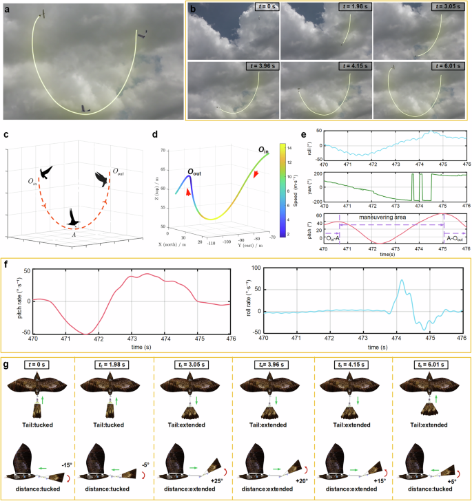
a Outdoor flight test trajectory of large angle dive and climb steeply maneuver (Supplementary Movie 12). b The time series of the outdoor flight trajectory for the large angle dive and climb steeply maneuver, where the somersault enters at t = 0 and exits at t = 6.01 s, takes 6.01 s for this maneuver trajectory. c Analysis of the large angle dive and climb steeply maneuver strategy; a. DFP M12: dive flight phase (Oin-A stage). The wing-tail distance l remains constant, with the horizontal tail St tucked and the pitch angle of the tail δe remains constant; b DFP M13: climb steeply phase (A-Oout phase). The wing-tail distance l gradually increases; the horizontal tail St gradually extends; the pitch angle of the tail δe gradually increases then decreases. d GPS measurement trajectory and velocity variation cloud map for the large angle dive and climb steeply maneuver. e The variations of roll angle, yaw angle, and pitch angle during the large angle dive and climb steeply maneuver. f The variations of pitch rate and roll rate during the large angle dive and climb steeply maneuver. g Drive control inputs corresponding to each time sequence of the large angle dive and climb steeply maneuver.
-
(2)
DFP M13: Climb steeply stage (A- Oout). In this stage, the flapping-wing robot is required to undergo a dual control mode involving steep climbing and transitioning back to normal flight. At the same time, as the airspeed decreases, it is necessary to restore the robot’s attitude and exit the jumping state of the robot. The required angle of attack for the robot gradually increases and subsequently decreases at this juncture. Consequently, the climb steeply strategy (as described in b-item analysis in Fig. 5c) is adopted until the robot’s attitude angle returns to its normal state.

The flight action space of the entire dive and climb steeply maneuver process is shown in Eq. (6), which is divided into two stages and three types of space operation instructions. According to the above flight control instructions, a large angle dive and climb steeply maneuver is achieved in the vertical plane. The outdoor maneuver flight trajectory is shown in Fig. 5a-b (Supplementary Movie 12). The corresponding control inputs for the driving surface and the angle variations over the time series are shown in Fig. 5g. At the same time, the GPS measurement trajectory of the dive and climb steeply maneuver is collected through the flight control module, as shown in Fig. 5d, and the attitude angle change is shown in Fig. 5e. The flapping wing robot undergoes a dive and a climb steeply. The pitch angle initially reaches a minimum value, subsequently attains a maximum value, and ultimately gradually returns to a horizontal state. The variations in pitch rate and roll rate are depicted in Fig. 5f. Throughout the entire maneuver, the pitch rate reached a maximum of 42.64°·s⁻¹ and a minimum of −50.77°·s⁻¹, while the roll rate peaked at 71.86°·s⁻¹ and dipped to a minimum of −41.48°·s⁻¹. This maneuver has undergone multiple repeated experiments, and its performance has been thoroughly validated.
Flight tests demonstrate that the above nine maneuver actions exhibit better maneuverability. Compared to other flapping-wing aircraft, the bionic flapping-wing aircraft designed in this study shows further enhanced maneuverability. A comparison of its maneuverability performance indicators (such as pitch rate and roll rate) with those of other flapping-wing aircraft can be found in Supplementary Information (Supplementary Notes 4).
Discussion
In this study, a biomimetic flapping-wing robot is designed to achieve agile maneuvering flight by coordinating the control of wing-tail distance and tail posture, inspired by natural raptors’ ability to adjust their COG and AC through body, head, leg movements, as well as the deformation of their wings7,32. Based on this premise, the dynamic theory is employed to analyze the configuration changes that occur during maneuvering, thereby facilitating the development of a flight control strategy capable of enabling diverse high maneuverability flights. The rationality of the control strategy has been substantiated and validated through experimental investigations conducted on a biomimetic flapping-wing robot with variable configuration. Additionally, an exploratory discussion on methods for maintaining lateral stability and achieving high longitudinal maneuverability during maneuvers is conducted.
Firstly, it is well-established that aircraft wings are typically designed with a specific dihedral angle to ensure lateral stability in accordance with principles of flight dynamics29. This study mainly focuses on the longitudinal maneuverability, therefore, it is necessary for flapping wing robots to have an appropriate wing dihedral angle. The flapping stroke angle range between −5° and 40° has been established, taking into consideration the dimensions and structural characteristics of the prototype. The schematic diagram of the flapping stroke angle is shown in Fig. 2b. The reference position for this flapping stroke angle lies within the horizontal plane direction, with a median value set at 17.5°. This median angle serves as the equivalent wing dihedral angle, providing good rolling stability for the robot during flight. The range of wing flapping stroke angles during motion determines both the magnitude and direction of generated aerodynamic forces while also influencing pitch stability of the robot.
Secondly, based on the analysis of flight data, it can be obtained that the stall angle of attack for the flapping-wing robot is approximately 35°. The maximum pitch angle reaches 32° when the wing-tail distance is increased by 20 cm, as depicted in Fig. 7. The further increase in this distance has the potential to induce structural instability, thereby adversely impacting flight stability. Throughout the process of increasing the wing-tail distance from 0 to 20 cm, there is a displacement in the COG of the robot from 12 cm to 17 cm relative to the leading edge beam, while AC position from 15 cm to 17.51 cm. Consequently, as the wing-tail distance increases, there is a gradual reduction in distance between the COG and AC from an initial value of 3 cm down to merely 0.51 cm. In accordance with balance torque formula (7), such decrease leads to diminished downward torque exerted by the wing and making it easier to achieve the figure of “8” somersaults compared to conventional flapping-wing robots.
where T represents a complete flapping cycle, Flift, Ftail are the average lift generated by the wings and tail respectively; dFlift·l1, dFtail·l2 are the instantaneous small pitch moment generated by Flift, Ftail relative to the robot’s COG.
Finally, our experiment results are consistent with previous theoretical research on bird flight, indicating that the tail of birds have the function of controlling pitch torque and maintaining balance, which can change the maneuverability and stability during flight33,34,35. The maneuvering strategy during the rapid dive and steep climb at a large angle involves tail tucking upon entering the dive phase, extending the tail when reaching the lowest point during the steep climb phase, while simultaneously increasing the wing-tail distance. According to the balance torque formula (7), when the robot initiates a dive maneuver, it undergoes tail tucking resulting in a reduction of the tail area by half compared to its extended state. Consequently, there is a reduction in aerodynamic force acting on the tail. At this time, the upward torque generated by the tail is insufficient to balance the downward torque generated by the wing, causing the robot to dive sharply downwards. When the robot reaches the lowest point, the tail extends, enabling a greater upward torque to be achieved. Simultaneously, the wing-tail distance increases, thereby augmenting the upward torque and facilitating rapid transitions in diving phases, ultimately enabling an upward maneuver to be executed by the robot. Compared to conventional flapping-wing robots, the tucked tail enables a greater diving moment during the diving phase, thereby accelerating the speed of entering this phase. In the climb steeply phase, the extended tail and the increase in the wing-tail distance can generate a greater upward torque. As a result, the time for entering and exiting maneuvers is shorter, resulting in stronger maneuverability. The experimental results also confirm the correctness of this conclusion.
The outdoor flight tests have achieved 9 typical longitudinal maneuvers, verifying the high maneuverability of the biomimetic flapping-wing robot with variable configuration. However, due to the frequent changes in control instructions by flight controllers during the maneuvering process, it becomes challenging to fully exploit the robot’s maneuvering potential and achieve optimal accuracy in the maneuvering process. To fully demonstrate the exceptional maneuvering potential of the biomimetic flapping-wing robot with variable configuration, it is essential to implement autonomous flight control systems for controlling and conducting maneuvering flights during flight testing. The proposed approach will effectively mitigate errors and misoperations resulting from human manipulation, thereby enhancing both accuracy and flexibility throughout the entire maneuvering flight process36.
Simultaneously, research will be conducted on the natural movement patterns of birds through wing morphing to explore the impact of autonomously morphing wings on maneuverability and stability during flight29,32,33, thereby enhancing the flight performance of biomimetic flapping-wing robots. Furthermore, birds exhibit diverse wing and tail forms during take-off, landing, gliding, and cruising flight29,32, which serves as inspiration for investigating flapping-wing robot research. In future research, in-depth exploration will be conducted in this area to study the adaptability of biomimetic flapping-robots with variable configuration for complex flight environments through autonomous deformation of wings and tail under different flight conditions.
Methods
The structure and material of wings and stiffness optimization
The structure and material of wings
In order to ensure that the wings have a certain stiffness layout after actual assembly in the prototype scheme, we embedded a cross layout carbon fiber rod group on the wings made of aviation umbrella cloth as the skin material. The layout and design details of the carbon fiber rods are shown in Fig. 6a. The leading edge beam of the inner wing section is constructed using 8 × 6 mm carbon fiber hollow round rods, while the outer section leading edge beam utilizes 4 × 2 mm carbon fiber hollow round rods to provide structural support for the entire wing surface. The trailing edge diagonal rod utilizes a 3 mm diameter carbon fiber round rod to effectively maintain tension across the entire wing surface. Additionally, six wing ribs with a thickness of 2 mm are employed to optimize the aerodynamic layout of the entire wing surface. The skeleton is enveloped in a layer of aviation parachute fabric with high elastic modulus and tear resistance, which facilitates lift and thrust generation during flapping.

a The main structural components of wings. b Due to the influence of the leading edge beam on the stiffness of the wings under the same layout conditions, wings with different stiffness were designed for comparative testing. c Optimization testing of wing thrust. Placing wings with different stiffness on an experimental testing platform for comparative testing.
Optimization design of wing’s stiffness
In order to compare and study the impact of different wing’s stiffness layouts on wing’s performance and determine the optimal design scheme for high thrust wings, we proposed three wing’s structure schemes with different stiffness layouts as listed in Fig. 6b based on prototype design experience. According to the experimental test data analysis in Fig. 6c, it can be observed that among the three types of wings compared, the wing with a leading edge beam of 8 × 6 mm produces the highest thrust. Outdoor flight tests have also fully verified that using this type of wing can better complete various types of high maneuverability actions.
The structure and material of morphing tail and parameter design
The structure and material of morphing tail
The role of the avian tail in the process of flight is of utmost importance, as it exhibits distinct morphologies under varying flight conditions. However, current flapping wing robots are constrained by a singular tail configuration and lack the capability to dynamically deform similar to avian tails, thereby hindering their adaptability to diverse flight requirements33,37. In order to meet the flight requirements under different flight conditions, a deformable tail system is designed, which includes a driving module, attitude adjustment module, deformation module, etc. The driving module comprises of two driving servos, two connecting rods, and a servo mounting plate. Meanwhile, the attitude adjustment module consists of a rotary connector and a pitch connector. The rotary connector is capable of rotating relative to the driving module around the rotation axis to achieve tail yaw motion, while the pitch connector facilitates pitch motion relative to the rotation component around the rotation axis. The deformation module comprises artificial feather connectors, artificial feathers, sliding connectors, deformation driving linkages, and deformation driving servos. By driving the deformation driving servos, the artificial feathers can achieve tucking and extending movements. The tail deformation structure is shown in Fig. 2d.
The parameter design of morphing tail
Birds typically rely on their tail for maneuvering during flight, which plays a pivotal role in ensuring flight stability and enhancing maneuverability. Moreover, they possess the ability to modify their flight direction through alterations in both the angle and morphology of their tail38,39. Due to the exceptional lateral stability provided by the T-shaped tail40,41, it has been selected as the optimal choice for the flapping wing robot in this study. In order to ensure that the robot has a certain longitudinal static stability during normal flight and provides sufficient control torque during maneuvering flight, it is required that the tail has an appropriate tail capacity. The T-shaped tail is composed two parts: a horizontal tail and a vertical tail. Its geometric parameters can be obtained based on the tail capacity, and according to the definitions of horizontal tail capacity and vertical tail capacity:
where Sht and Svt are the areas of the horizontal tail and vertical tail, lht and lvt are the force arms of the horizontal tail and vertical tail, respectively. Sw is the area of the wing, L is the span length of the wing, and c is the average aerodynamic chord length of the wing.
The tail capacity can generally be selected based on the average value of the same type of aircraft or a specific type of prototype42. Based on the aforementioned analysis, the calculated area Sht of the horizontal tail is 0.14 m2, while the tucked area measures 0.068 m2. The tucking and extending ratio is approximately 0.5, and lastly, the area Svt of the vertical tail amounts to 0.04 m2.
Theoretical analysis of longitudinal flight dynamics
First, we need to calculate the variation of longitudinal moment generated by the wing as a function of the wing-tail distance ∆l.
The relationship between the distance ∆xac of the AC moving backwards and the wing-tail distance ∆l variation is:
where XF, XF, ∆l are the distances from the AC to the leading edge of the wing before and after the change in wing-tail distance, respectively. These distances are expressed as a percentage of chord length; kF: a correction coefficient; Sw: Wing area; SH: Area of horizontal tail; LH: The force arm of the tail relative to the COG, which is the distance from the COG to the AC of the horizontal tail; c: Wing chord length.
The relationship between the distance ∆xac of the COG moving backwards and the wing-tail distance ∆l variation is:
where mw is the weight of the wings and fuselage, and mt is the weight of the tail; x0 and x1 respectively represent the distance between the COG of the flapping robot and the leading edge of the wing before and after the change in wing-tail distance.
The longitudinal flight moment generated by the wing during flight is obtained from the aerodynamic formula as follows:
where ρ is the air density, v is flight speed, Sw is wing area, CLα.w is the slope of the lift line of the wing, αw is the angle of attack of the wing during flight; xac and xc.g are the distances from the AC and COG to the leading edge of the wing before the change in wing-tail distance, respectively.
Then, we need to calculate the variation of longitudinal moment generated by the tail as a function of the wing-tail distance ∆l.
The longitudinal flight moment generated by the tail during flight is obtained from the aerodynamic formula as follows:
where St is the area of the horizontal tail, CLα.t is the slope of the lift line of the tail, αt is the angle of attack of the tail, lht is the force arm of horizontal tail when the wing-tail distance is tucked.
Third, the angle of attack corresponding to robot torque balance as a function of the wing-tail distance ∆l, and the pitch angle ∆αt of the tail is obtained.
The angle of attack αw corresponding to robot torque balance as a function of the wing-tail distance ∆l is as follows:
The relationship between the angle of attack of the wings and the wing-tail distance can be obtained as shown in Fig. 7:

(the horizontal axis ∆l represents the change of wing-tail distance; the vertical axis represents the angle of attack of the wings, ∆αt is the pitch angle of the tail).
Finally, the principles of high-maneuver flight dynamics for the flapping-wing aircraft are analyzed.
-
(1)
Derivation and simplification of flight dynamics equations: The scalar form of the robot’s center of mass dynamics equations in the trajectory coordinate system can be derived from flight dynamics, as shown in formula(15).
$$\left.\begin{array}{c}m\frac{{{\rm{d}}}V}{{{\rm{d}}}t}=T\,\cos (\alpha + \varphi )\cos \beta - D - mg\,\sin \gamma \\ mV\,\cos \gamma \frac{{{\rm{d}}}\chi }{{{\rm{d}}}t}=T[\sin (\alpha + \varphi )\sin \mu - \,\cos (\alpha + \varphi )\sin \beta \,\cos \mu ] + C\,\cos \mu + L\,\sin \mu \\ - mV\frac{{{\rm{d}}}\gamma }{{{\rm{d}}}t}=T[ - \,\sin (\alpha + \varphi )\cos \mu - \,\cos (\alpha + \varphi )\sin \beta \,\sin \mu ] + C\,\sin \mu - L\,\cos \mu + mg\,\cos \gamma \end{array}\right\}$$(15)The longitudinal flight of a robot refers to a flight that does not tilt or slide, and the symmetry plane coincides with the vertical plane where COG trajectory is located. Under these conditions, Eq. (15) can be simplified accordingly.
$$\phi =\mu =0,\,\beta =0,\,\frac{{{\rm{d}}}\chi }{{{\rm{d}}}t}=0$$(16)$$\left.\begin{array}{c}m\frac{{{\rm{d}}}V}{{{\rm{d}}}t}=T - D - mg\,\sin \gamma \\ - mV\frac{{{\rm{d}}}\gamma }{{{\rm{d}}}t} = - L + mg\,\cos \gamma \end{array}\right\}$$(17) -
(2)
Dynamic analysis of high maneuverability flight: The force analysis and detailed dynamic analysis of flapping wing robots are presented in Supplementary Information (Supplementary Notes 2). The dynamic analysis in the upper half of the figure of “8” somersault maneuver is as follows:
In the direction of X:
In the direction of Z:
So
From point A to any point on the trajectory, according to the theorem of kinetic energy:
According to Eqs. (20) and (21), the relationship between the angle of attack and phase angle in the upper half of the figure of “8” somersault can be found in Supplementary Information (Supplementary Notes 2).
The flight control strategies for each stage in the upper half of the somersault maneuver are obtained as follows: a. DFP M1:In the beginning stage of maneuver (Oin-A stage), the flapping frequency increases and the flight speed increases; b. DFP M2: In the upper half of the somersault maneuver, during the ascent and pull-up phase (A-B phase), the wing-tail distance l gradually increases, accompanied by an extension of the horizontal tail St and a gradual increase in the pitch angle of the tail δe. Subsequently, the wing-tail distance l gradually decreases to an appropriate distance, while the horizontal tail St remains extended and the pitch angle of the tail δe gradually decreases; c. DFP M3: In the upper half of the somersault maneuver, during the ascent and inverted flight phase (B-C phase), the wing-tail distance l exhibits a non-monotonic variation, initially increasing before subsequently decreasing. Simultaneously, the horizontal tail area St extends, while the pitch angle of the tail δe undergoes an initial decrease followed by an increase; d. DFP M4: In the upper half of the somersault maneuver, during the dive and inverted flight phase (C-D phase), the wing-tail distance l progressively increases, accompanied by an extension of the horizontal tail St. Simultaneously, there is a gradual increment in the pitch angle of the tail δe; e. DFP M5: In the upper half of the somersault maneuver, during the dive and pull-up phase (D-A phase), the wing-tail distance l gradually decreases, while the horizontal tail St gradually extends and the pitch angle of the tail δe gradually increases.
The dynamic analysis in the lower half of the figure of “8” somersault maneuver is as follows:
In the direction of X:
In the direction of Z:
So
From point A to any point on the trajectory, according to the theorem of kinetic energy:
According to Eqs. (24) and (25), the relationship between the angle of attack and phase angle in the lower half of the figure of “8” somersault can be found in Supplementary Information (Supplementary Notes 2).
The flight control strategies for each stage in the lower half of the somersault maneuver are obtained as follows: f. DFP M6: In the lower half of the somersault maneuver, during the dive and descent phase (A-E phase), the wing-tail distance l remains in a contracted state, while the horizontal tail St extends and the pitch angle of the tail δe gradually decreases. Subsequently, the wing-tail distance l gradually increases, while the horizontal tail St extends and the pitch angle of the tail δe continues to decrease; g. DFP M7: In the lower half of the somersault maneuver, during the descent and inverted flight phase (E-F phase), the wing-tail distance l gradually increases, while the horizontal tail St extends and the pitch angle of the tail δe remains in a certain downward state; h. DFP M8: In the lower half of the somersault maneuver, during the inverted flight and pull-up phase (F-G phase), the wing-tail distance l gradually decreases, while the horizontal tail St extends and the pitch angle of the tail δe remains in a certain downward state; i. DFP M9: In the lower half of the somersault maneuver, during the pull-up and ascent phase (G-A phase), the wing-tail distance l gradually increases, while the horizontal tail St extends and the pitch angle of the tail δe gradually increases; j. DFP M10: In the revert to level flight phase of somersault maneuvers (A-Oout phase), the wing-tail distance l gradually decreases, while the horizontal tail St extends and the pitch angle of the tail δe gradually increases.
The usefulness and advantage of the proposed tail mechanism
Compared with traditional flapping-wing aircraft that can only adjust maneuverability by changing the tail area and pitch angle, the proposed tail mechanism in this study demonstrates unique advantages. The high-maneuverability flight behaviors described in this study are not solely related to changes in the aircraft’s center of gravity but are also influenced by the tail area and the pitch angle of the tail. While increasing the tail area and pitch angle can indeed enhance the pitching moment and improve the longitudinal maneuverability of the aircraft to some extent, excessive increases in these parameters can lead to higher drag during flight, reduce the required flight speed for maneuvers, and consequently diminish the aircraft’s overall maneuverability. Additionally, the increased drag raises the power consumption of the aircraft, shortening flight duration. Furthermore, due to structural design constraints, the tail area and pitch angle cannot be increased indefinitely. In contrast, adjusting the pitching moment by altering the center of gravity not only meets structural design requirements but also minimizes drag during flight. This approach ensures flight speed while extending flight endurance.
As illustrated in Fig. 8, the longitudinal moment characteristics of the horizontal tail are analogous to those of the wing, with the distinction that the horizontal tail typically employs a symmetric airfoil and generally lacks aerodynamic or geometric twist. When the elevator is undeflected, the pressure center coincides with the aerodynamic focus, resulting in a zero pitching moment for the horizontal tail itself. However, when the horizontal tail is mounted at the rear of the fuselage or on the vertical tail, its flow field is influenced by the upstream flow, thereby affecting its longitudinal moment characteristics.

The schematic diagram of angular parameters during the flight of a flapping-wing aircraft.
First, the magnitude of the average flow velocity in the horizontal tail region is affected by energy losses as the airflow passes over preceding components of the aircraft, resulting in a velocity reduction. If kq denotes the velocity retardation factor, the velocity at the horizontal tail can be expressed as:
Second, considering the general case, the horizontal tail has an installation angle ϕt (by convention, ϕt < 0 when the horizontal tail chord is deflected downward relative to the wing chord extension or fuselage axis, and ϕt > 0 otherwise). Taking these factors into account, the effective angle of attack at the horizontal tail is given by:
where αt is the angle of attack of the wing. The aerodynamic lift Lt acting on the horizontal tail can be expressed as:
The distance from the aerodynamic force application point on the extendable tail to the center of gravity along the fuselage longitudinal axis can be written as:
where l0 is the initial length of the tail when not extended, and Δl is the extension distance of the tail. The longitudinal moment generated by the aerodynamic lift of the horizontal tail about the aircraft’s center of mass is approximately:
where CLα,t is the lift coefficient slope of the horizontal tail, lvt is the distance from the horizontal tail aerodynamic focus to the center of mass along the fuselage longitudinal axis, and St is the area of the horizontal tail (including the elevator). By dividing the longitudinal moment ML,t by qSc, the moment coefficient is obtained as:
From the above Eq. (31), it is evident that the longitudinal pitching moment experienced by the aircraft is proportional to the tail pitch angle ϕt, the tail area St, and the tail extension distance Δl. However, the aircraft is also subject to aerodynamic drag during flight. The drag force Dt acting on the horizontal tail can be expressed as:
The longitudinal moment about the aircraft’s center of gravity due to the aerodynamic drag of the horizontal tail can be approximated as:
From the above equation, it is evident that the aerodynamic drag experienced by the aircraft during flight is positively correlated with the tail pitch angle ϕt and the tail area St, but independent of the tail extension distance. Moreover, when the tail is extended, the moment arm of the aerodynamic lift increases, allowing the aerodynamic force required to maintain aircraft balance to be appropriately reduced. Consequently, the tail pitch angle ϕt can be decreased, thereby reducing the drag encountered during flight.
The analysis demonstrates that enhancing aircraft maneuverability by adjusting the tail extension distance does not incur additional drag or power consumption. Compared to methods that increase maneuverability by enlarging the tail pitch angle or tail area, this approach results in lower drag, higher flight speeds, longer flight durations, and superior overall performance.
Data availability
The authors declare that the data supporting the findings of this study are available within the paper and its supplementary information files.
References
Chin, D. D. & Lentink, D. Birds repurpose the role of drag and lift to take off and land. Nat. Commun. 10, 5354 (2019).
De Croon, G. Flapping wing drones show off their skills. Sci. Robot. 5, eabd0233 (2020).
Abdulrahim, M. & Lind, R. Using Avian Morphology to Enhance Aircraft Maneuverability, In AIAA Atmospheric Flight Mechanics Conference and Exhibit (AIAA, 2006).
Rader, J. A. & Hedrick, T. L. Morphological evolution of bird wings follows a mechanical sensitivity gradient determined by the aerodynamics of flapping flight. Nat. Commun. 14, 7494 (2023).
Han, J.-H., Han, Y.-J., Yang, H.-H., Lee, S.-G. & Lee, E.-H. A review of flapping mechanisms for avian-inspired flapping-wing air vehicles. Aerospace 10, 554 (2023).
Chu, L. et al. Design, modeling, and control of morphing aircraft: A review. Chinese. J. Aeronaut. 35, 220–246 (2022).
Harvey, C., Baliga, V. B., Wong, J. C. M., Altshuler, D. L. & Inman, D. J. Birds can transition between stable and unstable states via wing morphing. Nature 603, 648–653 (2022).
Wissa, A. Trade-offs between stability and manoeuvrability in bird flight. Nature 603, 579–580 (2022).
Zufferey, R. et al. How ornithopters can perch autonomously on a branch. Nat. Commun. 13, 7713 (2022).
Ajanic, E., Feroskhan, M., Mintchev, S., Noca, F. & Floreano, D. Bioinspired wing and tail morphing extends drone flight capabilities. Sci. Robot. 5, eabc2897 (2020).
Chang, E., Matloff, L. Y., Stowers, A. K. & Lentink, D. Soft biohybrid morphing wings with feathers underactuated by wrist and finger motion. Sci. Robot. 5, eaay1246 (2020).
Di Luca, M., Mintchev, S., Heitz, G., Noca, F. & Floreano, D. Bioinspired morphing wings for extended flight envelope and roll control of small drones. Interface Focus 7, 20160092 (2017).
Barbarino, S., Bilgen, O., Ajaj, R. M., Friswell, M. I. & Inman, D. J. A review of morphing aircraft. J. Intell. Mater. Syst. Struct. 22, 823–877 (2011).
Jitsukawa, T., Adachi, H., Abe, T., Yamakawa, H. & Umezu, S. Bio-inspired wing-folding mechanism of micro air vehicle (MAV). Artif. Life. Robot. 22, 203–208 (2017).
Dufour, L., Owen, K., Mintchev, S. & Floreano, D. A drone with insect-inspired folding wings, In 2016 IEEE/RSJ International Conference on Intelligent Robots and Systems (IROS), 1576–1581 (IEEE, 2016).
Ramezani, A., Chung, S.-J. & Hutchinson, S. A biomimetic robotic platform to study flight specializations of bats. Sci. Robot. 2, eaal2505 (2017).
Fan, X., Breuer, K. & Vejdani, H. Wing fold and twist greatly improves flight efficiency for bat-scale flapping wing robots, In 2021 IEEE/RSJ International Conference on Intelligent Robots and Systems (IROS), 7391–7397 (IEEE, 2021).
Ruiz, C., Acosta, J. A. & Ollero, A. Optimal elastic wing for flapping-wing robots through passive morphing. IEEE Robot. Autom. Lett. 8, 608–615 (2023).
Savastano, E., Perez-Sanchez, V., Arrue, B. C. & Ollero, A. High-performance morphing wing for large-scale bio-inspired unmanned aerial vehicles. IEEE Robot. Autom. Lett. 7, 8076–8083 (2022).
Suarez, A., Grau, P., Heredia, G. & Ollero, A. Winged aerial manipulation robot with dual arm and tail. Appl. Sci. 10, 4783 (2020).
Bena, R. M., Yang, X., Calderón, A. A. & Pérez-Arancibia, N. O. High-performance six-DOF flight control of the bee$^{++}$: an inclined-stroke-plane approach. IEEE Trans. Robot. 39, 1668–1684 (2023).
Ajanic, E., Paolini, A., Coster, C., Floreano, D. & Johansson, C. Robotic avian wing explains aerodynamic advantages of wing folding and stroke tilting in flapping flight. Adv. Intell. Syst. 5, 2200148 (2023).
Chen, A., Song, B., Wang, Z., Xue, D. & Liu, K. A novel actuation strategy for an agile bioinspired FWAV performing a morphing-coupled wingbeat pattern. IEEE Trans. Robot. 39, 452–469 (2023).
Calvente, L., Acosta, J. A. & Ollero, A. Design and manufacture of the wing folding mechanism for a bioinspired ornithopter, In 2021 Aerial Robotic Systems Physically Interacting with the Environment (AIRPHARO), 1–6 (IEEE, 2021).
Harvey, C., Baliga, V. B., Lavoie, P. & Altshuler, D. L. Wing morphing allows gulls to modulate static pitch stability during gliding. J. R. Soc. Interface. 16, 20180641 (2019).
Harvey, C., Baliga, V. B., Goates, C. D., Hunsaker, D. F. & Inman, D. J. Gull-inspired joint-driven wing morphing allows adaptive longitudinal flight control. J. R. Soc. Interface 18, 20210132 (2021).
Han, J., Hui, Z., Tian, F. & Chen, G. Review on bio-inspired flight systems and bionic aerodynamics. Chinese. J. Aeronaut. 34, 170–186 (2021).
Harvey, C. et al. A review of avian-inspired morphing for UAV flight control. Prog. Aerosp. Sci. 132, 100825 (2022).
Cheney, J. A. et al. Raptor wing morphing with flight speed. J. R. Soc. Interface. 18, 20210349 (2021).
Baliga, V. B., Szabo, I. & Altshuler, D. L. Range of motion in the avian wing is strongly associated with flight behavior and body mass. Sci. Adv. 5, eaaw6670 (2019).
Saveriano, M., Abu-Dakka, F., Kramberger, A. & Peternel, L. Dynamic movement primitives in robotics: a tutorial survey. Int. J. Robot. Res. 42, 1133–1184 (2023).
Lentink, D. et al. How swifts control their glide performance with morphing wings. Nature 446, 1082–1085 (2007).
Usherwood, J. R. et al. High aerodynamic lift from the tail reduces drag in gliding raptors. J. Exp. Biol. 223, jeb214809 (2020).
Thomas, A. L. R. The flight of birds that have wings and a tail: variable geometry expands the envelope of flight performance. J. Theor. Biol. 183, 237–245 (1996).
Mintchev, S. & Floreano, D. Adaptive morphology: a design principle for multimodal and multifunctional robots. IEEE Robot. Autom. Mag. 23, 42–54 (2016).
Feroskhan, M. & Go, T. H. Dynamics of sideslip perching maneuver under dynamic stall influence. Aerosp. Sci. Technol. 50, 220–233 (2016).
Perez-Sanchez, V., Gomez-Tamm, A. E., Savastano, E., Arrue, B. C. & Ollero, A. Bio-inspired morphing tail for flapping-wings aerial robots using macro fiber composites. Appl. Sci. 11, 2930 (2021).
Tay, W. B., Bijl, H. & Van Oudheusden, B. W. Biplane and tail effects in flapping flight. AIAA J 51, 2133–2146 (2013).
Nan, Y., Chen, Y., Mcglinchey, D. & Li, Y. Experimental studies of tail shapes for hummingbird-like flapping wing micro air vehicles. IEEE Access 8, 52622–52630 (2020).
Zhang, P., Zhu, J. & Zhu, Y. Analysis on hover control performance of t- and cross-shaped tail fin of x-wing single-bar biplane flapping wing. J. Robot. 2020, 1–13 (2020).
Guzman, M. M. et al. Design and comparison of tails for bird-scale flapping-wing robots, In 2021 IEEE/RSJ International Conference on Intelligent Robots and Systems (IROS), 6358–6365 (IEEE, 2021).
Raymer, D. Aircraft Design: A Conceptual Approach, Sixth Edition (AIAA, 2018).
Acknowledgements
The authors would like to thank Zhibai Xin, Haoyu Wang, Jizhou Jiang and Zhihao Wei for their continuous support when conducting flight testing and the writing process.This work is supported by the National Natural Science Foundation of China (Grant No. 62233001), Shenzhen excellent scientific and technological innovation talent training project (Grant No. RCJC20200714114436040), Program of Shenzhen Peacock Innovation Team (Grant No. KQTD20210811090146075), and the Basic Research Program of Shenzhen (JCYJ20241202123724032, JCYJ20240813104923031).
Author information
Authors and Affiliations
Contributions
Guangze Liu developed the concept and wrote the manuscript. Erzhen Pan helped to develop the concept. Wei Sun and Shihua Wang conducted and analyzed the flight test. Wenfu Xu and Lei Yan provided research guidance, funding support, and equipment support.
Corresponding authors
Ethics declarations
Competing interests
The authors declare no competing interests.
Peer review
Peer review information
Communications Engineering thanks Songnan Bai and the other, anonymous, reviewer(s) for their contribution to the peer review of this work. Primary Handling Editors: Miranda Vinay, Saleem Denholme, Rosamund Daw]. [A peer review file is available.]
Additional information
Publisher’s note Springer Nature remains neutral with regard to jurisdictional claims in published maps and institutional affiliations.
Rights and permissions
Open Access This article is licensed under a Creative Commons Attribution-NonCommercial-NoDerivatives 4.0 International License, which permits any non-commercial use, sharing, distribution and reproduction in any medium or format, as long as you give appropriate credit to the original author(s) and the source, provide a link to the Creative Commons licence, and indicate if you modified the licensed material. You do not have permission under this licence to share adapted material derived from this article or parts of it. The images or other third party material in this article are included in the article’s Creative Commons licence, unless indicated otherwise in a credit line to the material. If material is not included in the article’s Creative Commons licence and your intended use is not permitted by statutory regulation or exceeds the permitted use, you will need to obtain permission directly from the copyright holder. To view a copy of this licence, visit http://creativecommons.org/licenses/by-nc-nd/4.0/.
About this article

Cite this article
Liu, G., Pan, E., Sun, W. et al. Agile manoeuvrable flight via collaborative wing-tail adjustment of a flapping wing robot. Commun Eng 4, 141 (2025). https://doi.org/10.1038/s44172-025-00480-9
Received:
Accepted:
Published:
Version of record:
DOI: https://doi.org/10.1038/s44172-025-00480-9
